TMR shunt
a technology of shunt and shunt tube, which is applied in the field of tmr shunt, can solve the problems of coronary artery disease, heart attack and death, and impair the efficiency of heart pumping action,
- Summary
- Abstract
- Description
- Claims
- Application Information
AI Technical Summary
Benefits of technology
Problems solved by technology
Method used
Image
Examples
first embodiment
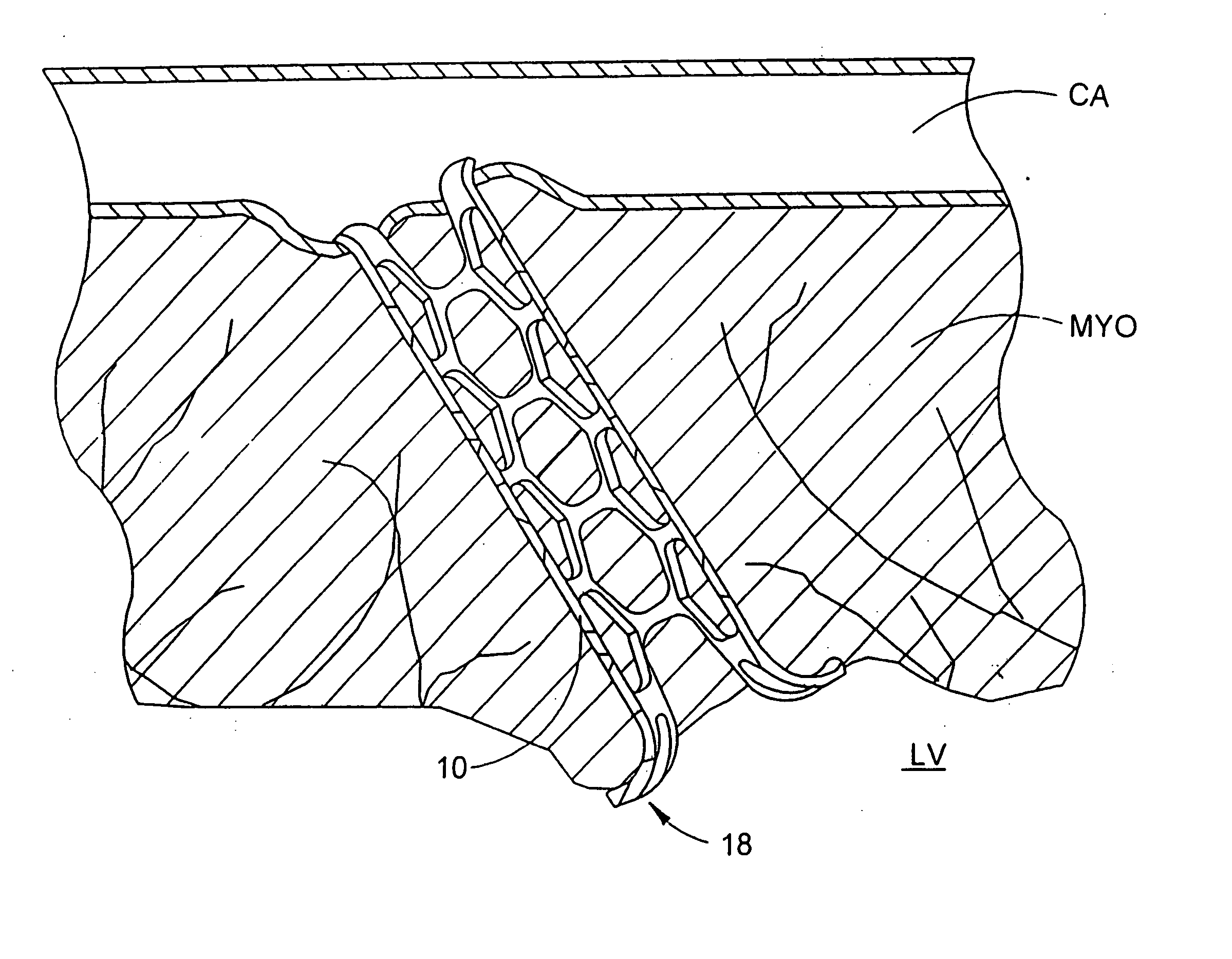
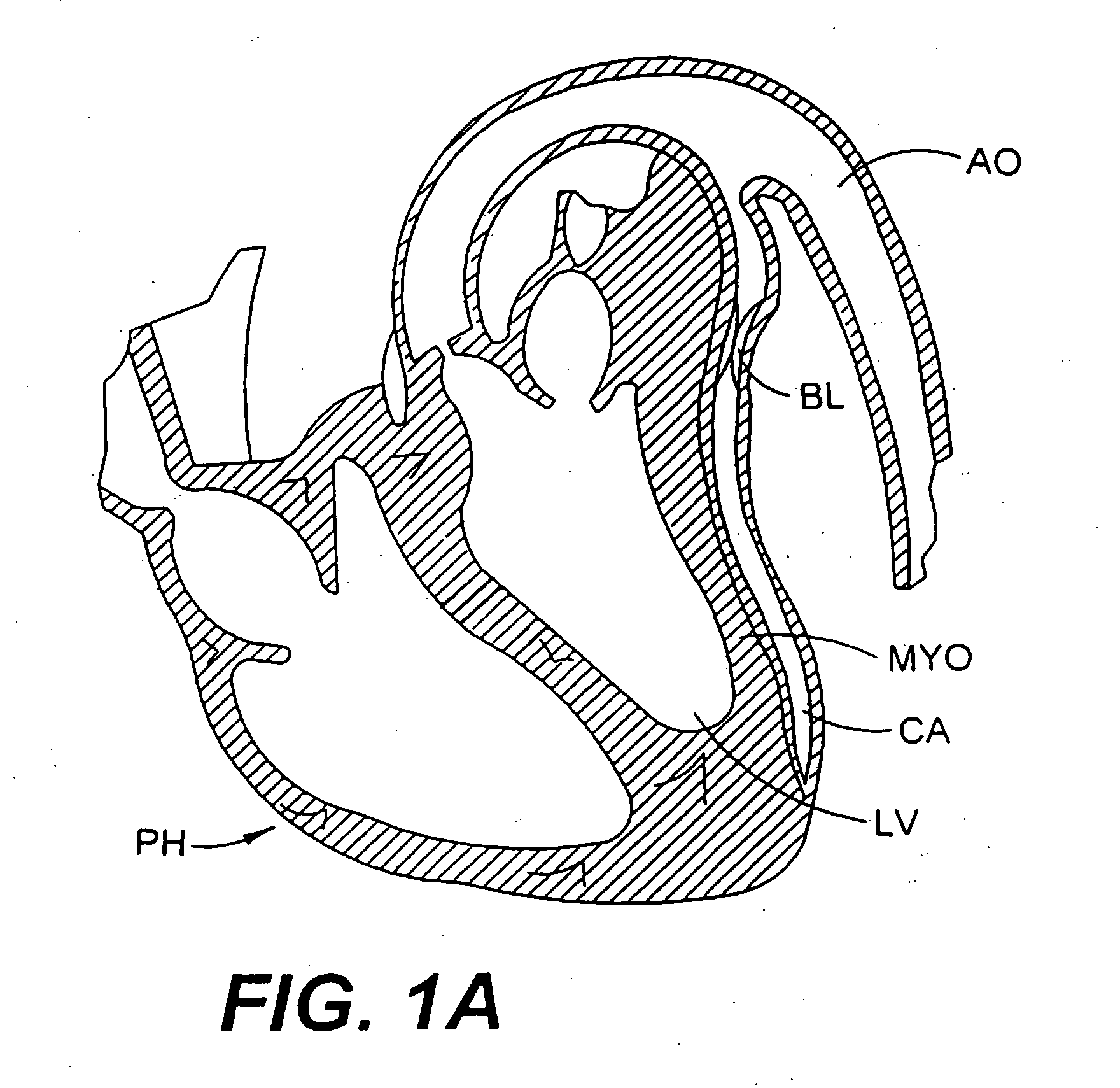
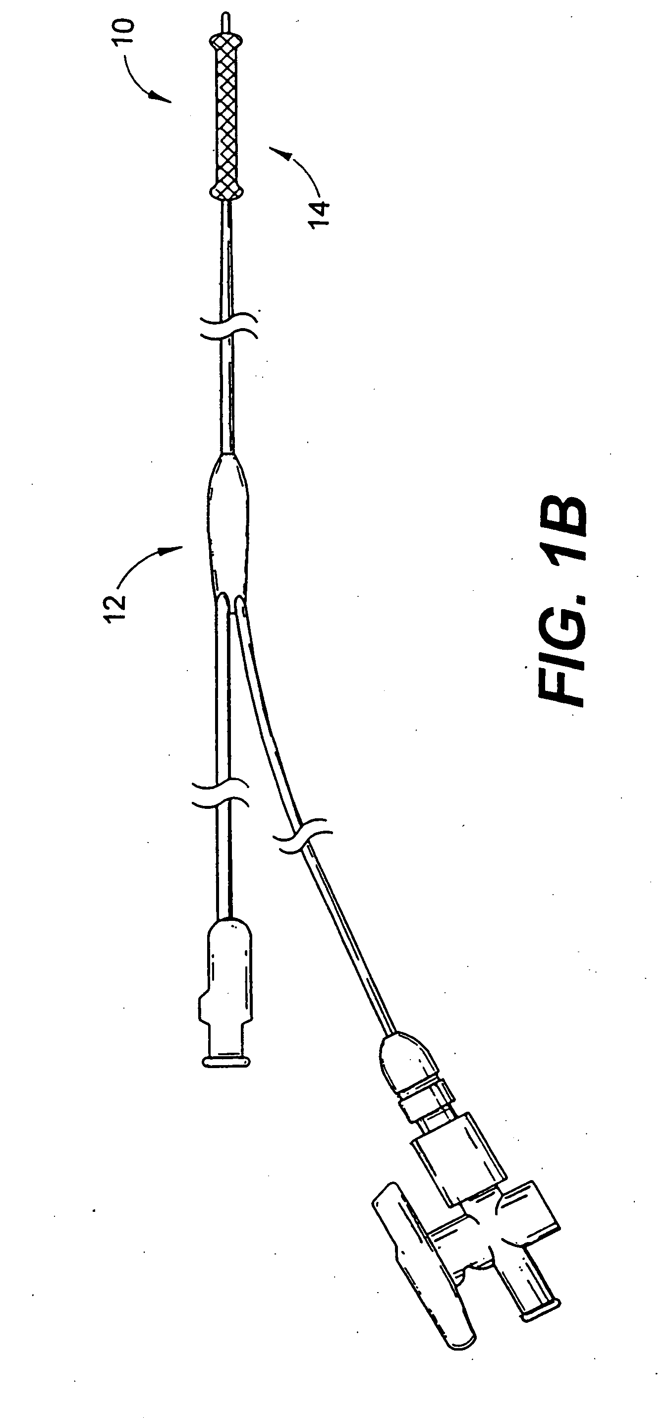
[0085] the present invention is illustrated in FIG. 1B. This embodiment is a balloon-expanded stent 10. The stent 10 is introduced as described below, using a high-pressure balloon catheter 12 to deploy the stent 10 once it is properly positioned in the myocardium MYO (FIG. 2). When the stent 10 is positioned inside the myocardial wall MYO, the balloon 14 is inflated to expand the stent 10 and open the conduit from the left ventricle LV into the coronary artery CA. The stent 10 can include attachment mechanisms not limited to hooks, barbs, flanges, large collars, suture holes and / or other means to ensure a seal is created between the coronary artery CA and the wall of the myocardium MYO and to prevent the threat of stent 10 migration. When the attachment of the stent 10 is completed, the remaining catheter assembly 12 is removed, leaving the stent 10 in place. Upon deflating the balloon 14, the stent 10 will remain open. Because of the shape of this stent 10, a dumbbell shaped ballo...
second embodiment
[0088] the stent or conduit incorporates a self-expanding stent 20, illustrated in FIGS. 5-8. The stent 20, having a retaining sheath 26 to hold it in a non-expanded configuration, is introduced into the wall of the myocardium MYO as follows. The stent delivery catheter 22 is advanced over a puncture mechanism 24 and into the wall of the myocardium MYO as described above. When the stent 20 is properly seated in the myocardial wall MYO, its retaining sheath 26 is withdrawn, allowing the stent 20 to expand and open a conduit from the ventricle LV to the coronary artery CA. This stent 20 also includes attachment mechanisms not limited to hooks, barbs, flanges, large collars, suture holes and / or other means to ensure a seal is created between the artery CA and the wall of the myocardium MYO, and to prevent the threat of stent 20 migration. When the positioning is completed, the remaining catheter assembly 22 is removed, leaving the stent 20 in place.
[0089] The self-expanding stent 20 mo...
third embodiment
[0091] the stent design, illustrated in FIGS. 9-11, incorporates attachment flanges or “legs”30 that expand after introduction into the myocardium to hold the stent 34 in place. The puncture instrument 32 and stent 34 are mated together and are advanced into the myocardial wall as a single unit. The puncture instrument's distal end 36 is shaped in a “nose-cone” configuration, which is responsible for containing the legs 30 of the stent 34 while it is being introduced into the wall of the myocardium. When the stent 34 is in the proper position in the myocardial wall, the nose cone 36 is pushed forward, releasing the attachment legs 30 of the stent 34. The internal diameter (ID) of the stent 34 is large enough to allow the nose cone 36 to pass back through. The stent 34 is then released from the catheter 38 and the catheter 38 is removed.
[0092]FIG. 9 illustrates the stent 34 mounted on the introducer catheter 38. The expanding legs 30 of the stent 34 are held in place by the nose cone...
PUM
 Abstract
Description
Claims
Application Information
 - R&D
- Intellectual Property
- Life Sciences
- Materials
- Tech Scout
- Unparalleled Data Quality
- Higher Quality Content
- 60% Fewer Hallucinations
Browse by: Latest US Patents, China's latest patents, Technical Efficacy Thesaurus, Application Domain, Technology Topic, Popular Technical Reports.
© 2025 PatSnap. All rights reserved.Legal|Privacy policy|Modern Slavery Act Transparency Statement|Sitemap|About US| Contact US: help@patsnap.com


