Behavior processor system and method

a processor and behavior technology, applied in the field of electronic design automation, can solve the problems of burdening the user, requiring some degree of user sophistication, and cumbersome current software simulation and hardware emulation/acceleration, and achieve the effect of reducing performan

Inactive Publication Date: 2006-06-01
VERISITY DESIGN
View PDF7 Cites 249 Cited by
  • Summary
  • Abstract
  • Description
  • Claims
  • Application Information

AI Technical Summary

Benefits of technology

[0014] Another object of the present invention is to be more resourceful than the virtual wires technology without the decrease in performance arising from the use of extra evaluation cycles for the transfer of inter-chip data.

Problems solved by technology

Nevertheless, current software simulation and hardware emulation / acceleration are cumbersome for the user because of the separate and independent nature of these processes.
However, co-simulators still have a number of drawbacks: (1) co-simulation systems require manual partitioning, (2) co-simulation uses two loosely coupled engines, (3) co-simulation speed is as slow as software simulation speed, and (4) co-simulation systems encounter race conditions.
First, partitioning between software and hardware is done manually, instead of automatically, further burdening the user.
Such a constraint requires some degree of sophistication by the user.
Second, co-simulation systems utilize two loosely coupled and independent engines, which raise inter-engine synchronization, coordination, and flexibility issues.
Values inside the modeled circuit at the register and combinational logic level are not available for easy inspection and downloading from one side to the other, limiting the utility of these co-simulator systems.
Thus, if the user wanted to switch between software simulation and hardware emulation / acceleration during a single debug session while being able to inspect register and combinational logic values, co-simulator systems do not provide this capability.
Third, co-simulation speed is as slow as simulation speed.
The additional overhead to coordinate the operation of these two engines adds to the slow speed of co-simulation systems.
Fourth, co-simulation systems encounter set-up, hold time, and clock glitch problems due to race conditions in the hardware logic element or hardware accelerator among clock signals.
This raises the uncertainty level of evaluation results as some logic elements evaluate data at some time period and other logic elements evaluate data at different time periods, when these logic elements should be evaluating the data together.

Method used


Image

  • Behavior processor system and method
  • Behavior processor system and method
  • Behavior processor system and method

Examples


Embodiment Construction

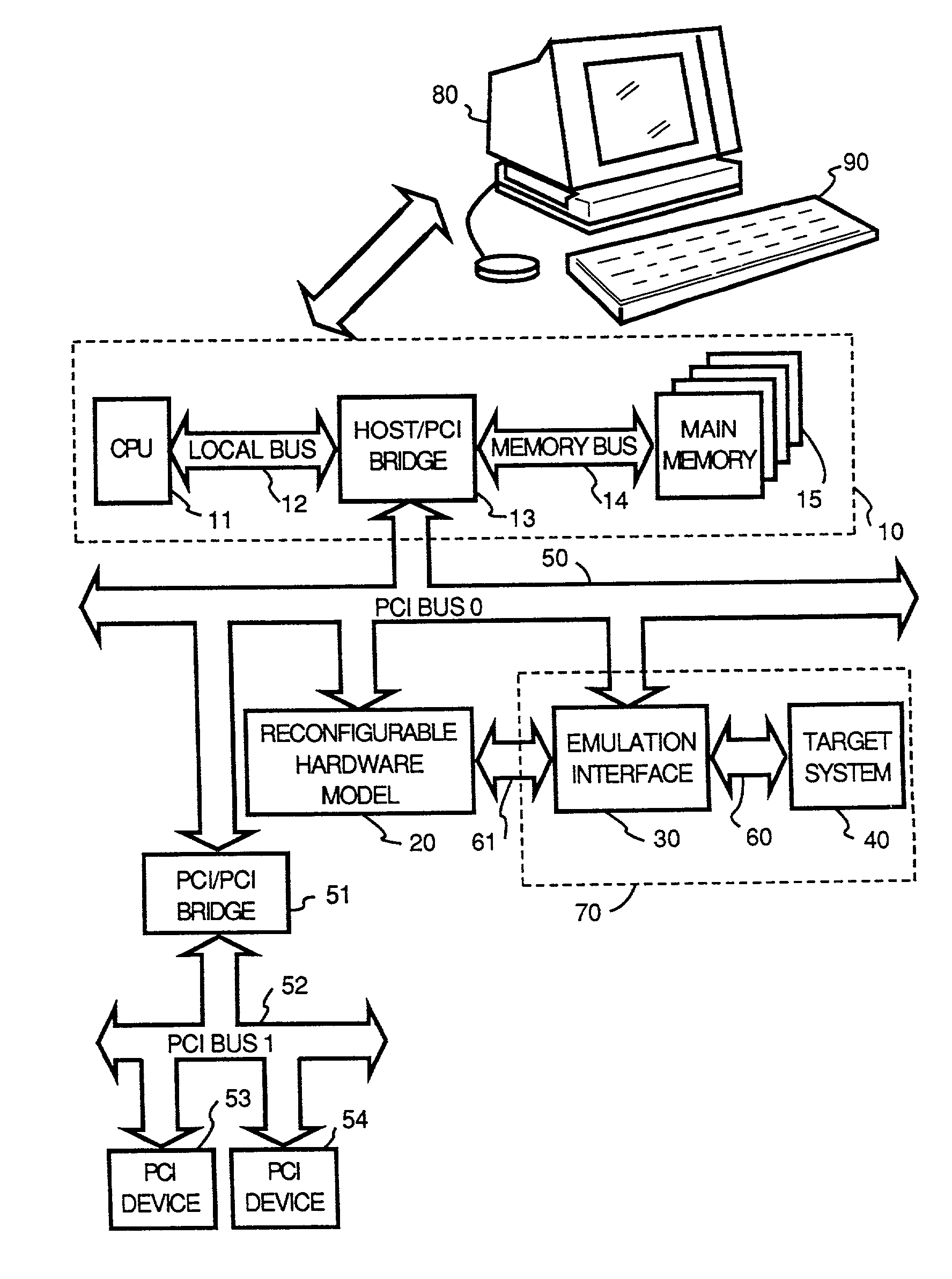
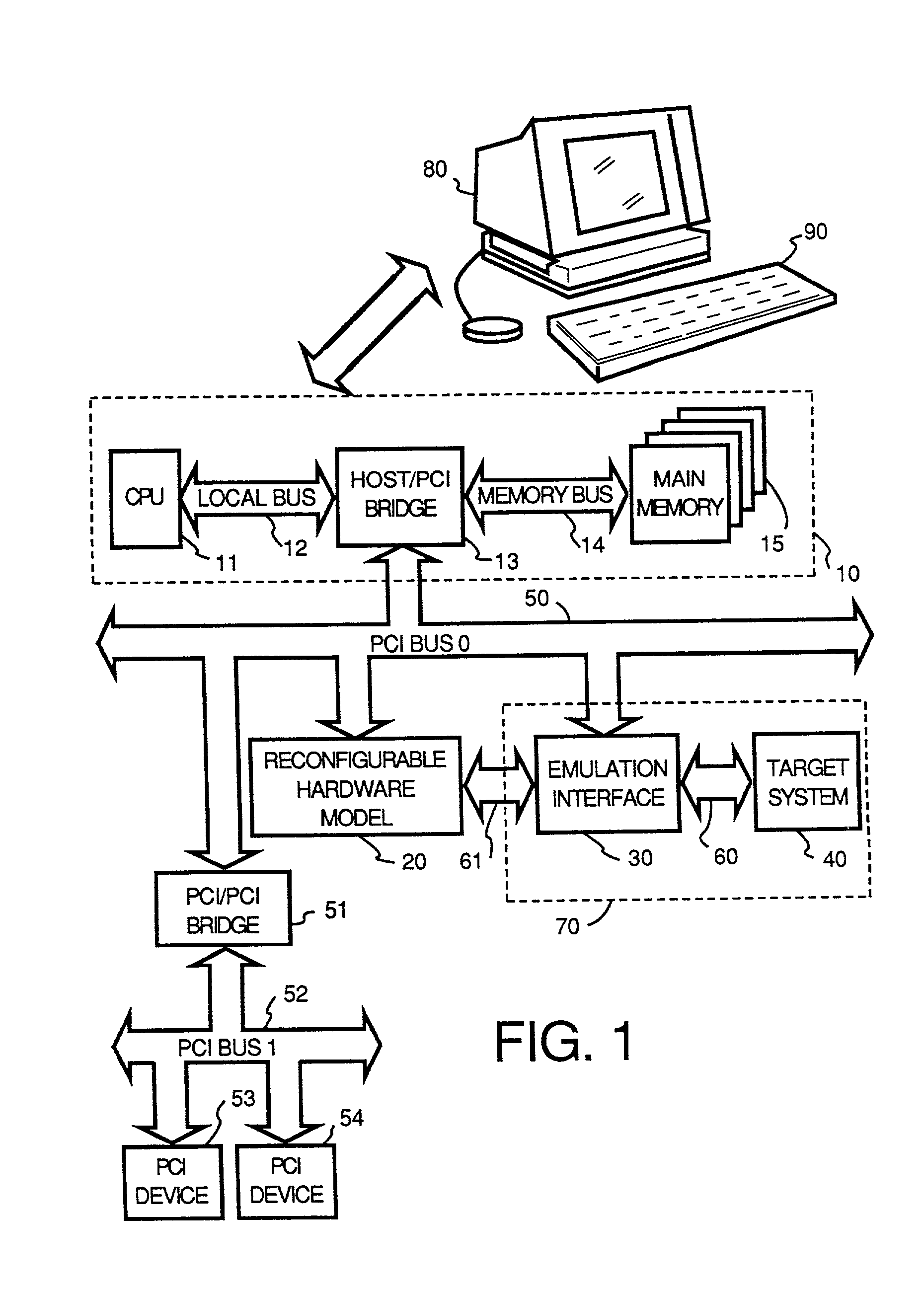
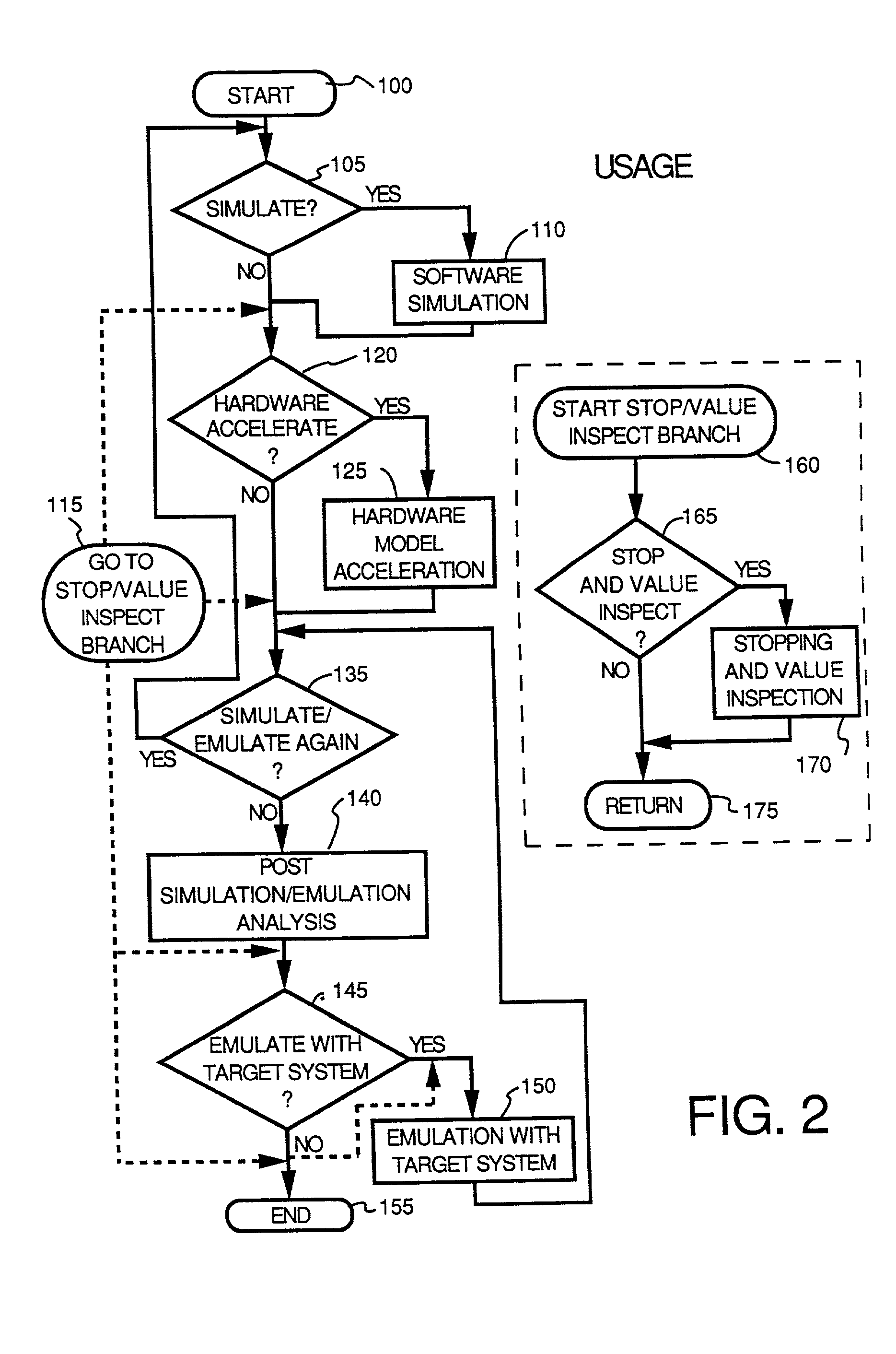
[0127] This specification will describe the various embodiments of the present invention through and within the context of a system called “SEmulator” or “SEmulation” system. Throughout the specification, the terms “SEmulation system,”“SEmulator system,”“SEmulator,” or simply “system” may be used. These terms refer to various apparatus and method embodiments in accordance with the present invention for any combination of four operating modes: (1) software simulation, (2) simulation through hardware acceleration, (3) in-circuit emulation (ICE), and (4) post-sinulation analysis, including their respective set-up or pre-processing stages. At other times, the term “SEmulation” may be used. This term refers to the novel processes described herein.

[0128] Similarly, terms such as “Reconfigurable Computing (RCC) Array System” or “RCC computing system” refers to that portion of the simulation / coverification system that contains the main processor, software kernel and the software model of t...


PUM


Abstract

The debug system described in this patent specification provides a system that generates hardware elements from normally non-synthesizable code elements for placement on an FPGA device. This particular FPGA device is called a Behavior Processor. This Behavior Processor executes in hardware those code constructs that were previously executed in software. When some condition is satisfied (e.g., If . . . then . . . else loop) which requires some intervention by the workstation or the software model, the Behavior Processor works with an Xtrigger device to send a callback signal to the workstation for immediate response.

Description

RELATED U.S. APPLICATION [0001] This is a continuation-in-part of U.S. patent application Ser. No. 09 / 900,124, filed Jul. 6, 2001, entitled “Inter-Chip Communication System”; which is a continuation-in-part of U.S. patent application Ser. No. 09 / 373,014, filed Aug. 11, 1999, entitled “VCD-on-Demand System and Method”; which is a continuation-in-part of U.S. patent application Ser. No. 09 / 144,222, filed Aug. 31, 1998, entitled “Timing-Insensitive and Glitch-Free Logic System and Method”.BACKGROUND OF THE INVENTION [0002] 1. Field of the Invention [0003] The present invention generally relates to electronic design automation (EDA). More particularly, the present invention relates to dynamically changing the evaluation period to accelerate design debug sessions. [0004] 2. Description of Related Art [0005] In general, electronic design automation (EDA) is a computer-based tool configured in various workstations to provide designers with automated or semi-automated tools for designing an...

Claims


Application Information

Patent Timeline
Patent Type & Authority Applications(United States)
IPC IPC(8): G06F17/50
CPCG06F17/5022G06F17/5027G06F2217/86G06F30/331G06F2117/08G06F30/33G06F9/455
Inventor TSENG, PING-SHENGGOEL, YOGESHHWANG, SU-JENLEE, JAMESSHEN, KUN-HSU
Owner VERISITY DESIGN
Why Eureka
Try Eureka