Method of producing analytical tool

a technology of analytical tools and tools, which is applied in the field of producing analytical tools, can solve the problems of high equipment and manufacturing cost, difficult to hydrophilically treat the side surfaces, and difficult to hydrophilically treat the side surfaces, and achieve the effect of low cost and simple structur

a technology of analytical tools and tools, which is applied in the field of producing analytical tools, can solve the problems of high equipment and manufacturing cost, difficult to hydrophilically treat the side surfaces, and difficult to hydrophilically treat the side surfaces, and achieve the effect of low cost and simple structur

US20060118403A1Inactive Publication Date: 2006-06-08ARKRAY INC

Image

  • Method of producing analytical tool
  • Method of producing analytical tool
  • Method of producing analytical tool

Examples


Embodiment Construction

[0026] The present invention relates to a method of producing an analytical tool which is mounted, in use, to an analytical apparatus. In the analytical apparatus, a sample liquid supplied to the analytical tool is analyzed by an optical method or an electrochemical method, for example.

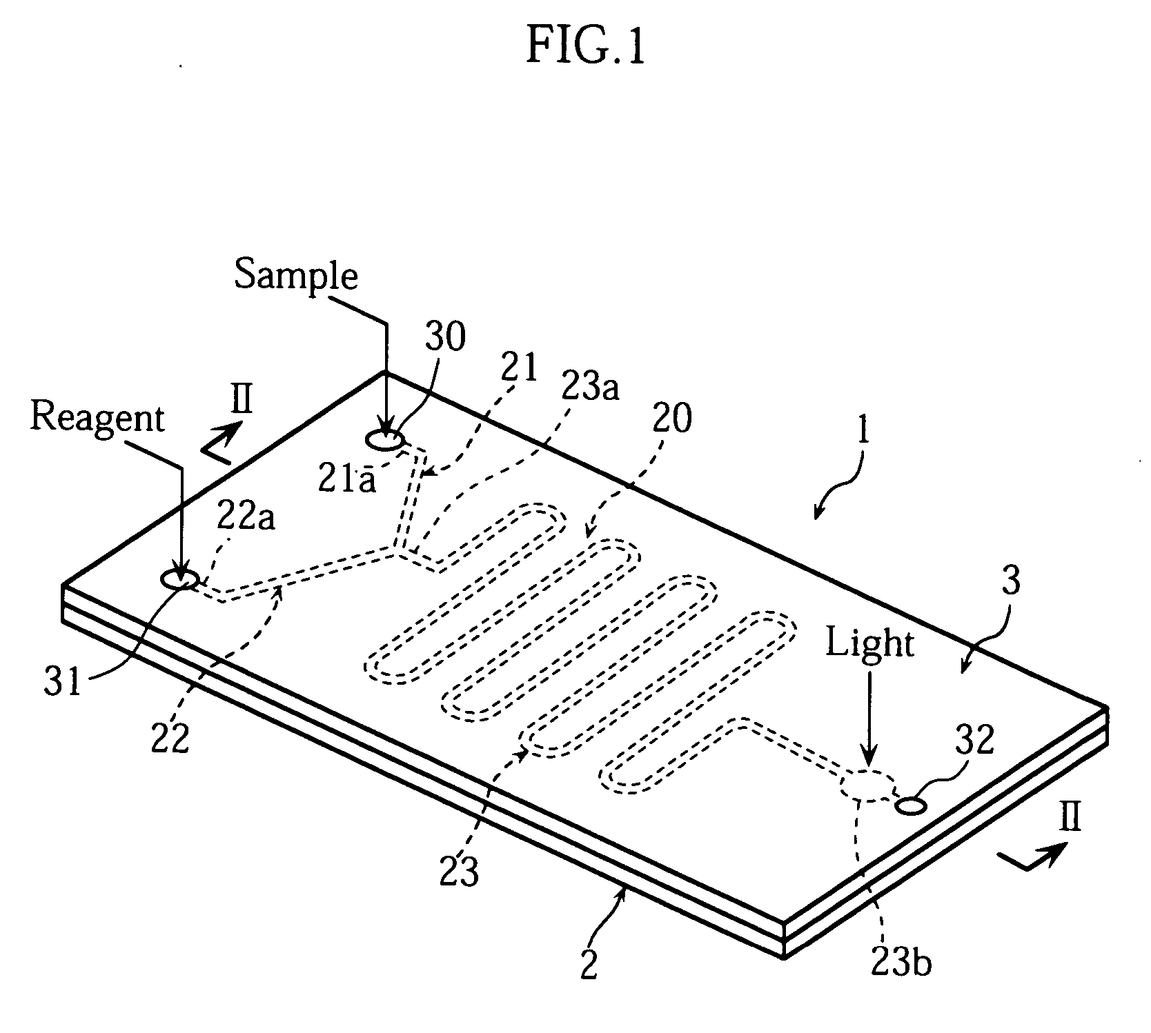
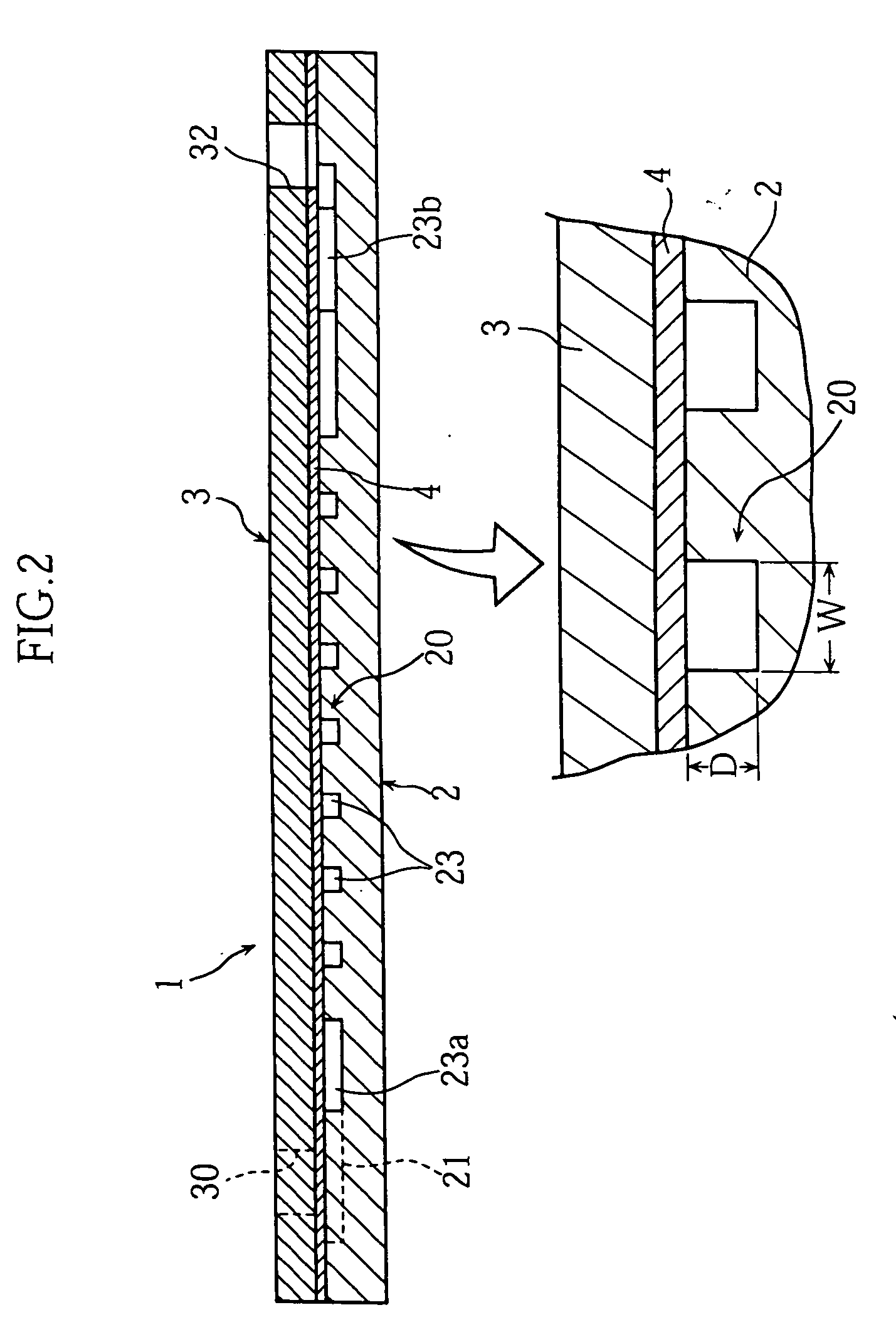
[0027]FIGS. 1-4 show an example of analytical tool to be produced by a method according to the present invention. The analytical tool 1 shown in the figures is a so-called microdevice and designed to perform analysis of a sample by an optical method. The microdevice 1, which serves to provide a reaction field, includes a substrate 2 formed with a groove 20, and a cover 3 bonded to the substrate 2 via an adhesive sheet 4 to cover the groove 20.

[0028] As better shown in FIGS. 1 and 4, the groove 20 includes a sample introduction path 21, a reagent introduction path 22 and a reaction path 23. The reaction path 23 has an end 23a connected to the sample introduction path 21 and the reagent introduction p...


PUM

PropertyMeasurementUnit
Temperatureaaaaaaaaaa
Partial pressureaaaaaaaaaa

Abstract

The invention relates to a method of producing an analytical tool having recesses (20) formed therein for moving a sample liquid, a base plate (2) made of polymeric material, and a cover laminated to the base plate (2) to cover the recesses (20). This producing method includes the step of applying a hydrophilic treatment to the inner surfaces of the recesses (20). The hydrophilic treatment includes a primary modifying operation for primarily modifying the properties of the inner surfaces of the recesses (20) by contacting a modifying gas with the inner surfaces of the recesses (20), and a secondary modifying operation for secondarily modifying the properties of the inner surfaces of the recesses (20).

Description

TECHNICAL FIELD [0001] The present invention relates to a method of producing an analytical tool which is used for analyzing a sample liquid and which is structured to move the sample liquid before the analysis. BACKGROUND ART [0002] In one type of analytical tool, a sample liquid is caused to move by capillary action. Such an analytical tool includes a capillary for producing a capillary force. To properly exert the capillary force onto a sample liquid, the inner surface of the capillary is hydrophilically treated. For example, in the structure shown in FIG. 9, a capillary 93 is formed by covering a groove 91 formed in a substrate 90 with a cover 92. In this case, the bottom surface 91a of the groove 91 and one surface 92a of the cover 92 are hydrophilically treated. The hydrophilization treatment with respect to the inner surface of the capillary 93 may be performed by ultraviolet irradiation, the application of a surface-active agent or plasma discharge such as glow discharge or ...

Claims


Application Information

Patent Timeline
08 Jun 2006
Publication
US20060118403A1
IPC
B29C59/10; B01J20/285; B01L3/00; G01N31/20; C08J7/00; C08J7/12; C08L101/00; G01N27/447; G01N30/32; G01N30/56; G01N30/60; G01N30/88; G01N37/00
CPC
B01L3/502707; B01L2200/12; B01L2300/0816; B01L2300/0867; B01L2300/0887; B01L2300/161; C08J7/12; G01N27/44752
Inventors
TAGUCHI, TAKAYUKI; KITAMURA, SHIGERU