Electron-emitting apparatus
a technology of electron-emitting apparatus and electron-emitting tube, which is applied in the direction of instruments, discharge tube luminescnet screens, process and machine control, etc. it can solve the problems of reducing the color purity and contrast of images in display, unnecessary electron emission, and damage to the electron-emitting apparatus, so as to avoid excessive electron emission and suppress unnecessary electron emission
- Summary
- Abstract
- Description
- Claims
- Application Information
AI Technical Summary
Benefits of technology
Problems solved by technology
Method used
Image
Examples
first embodiment
Structure
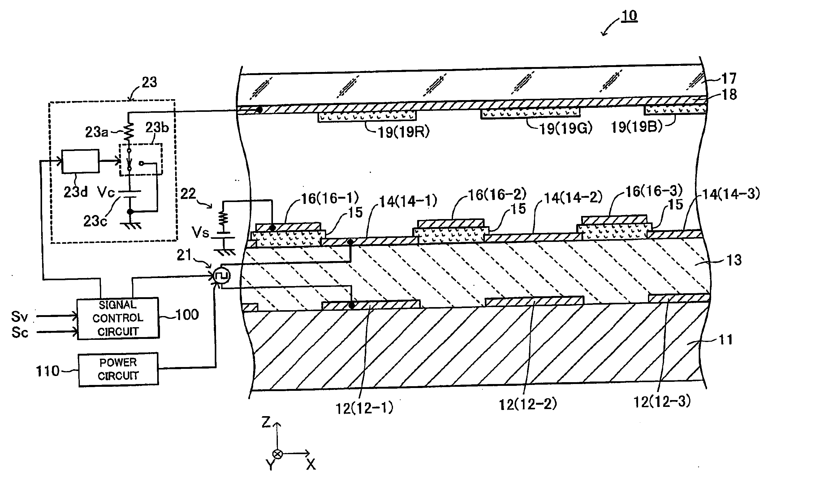
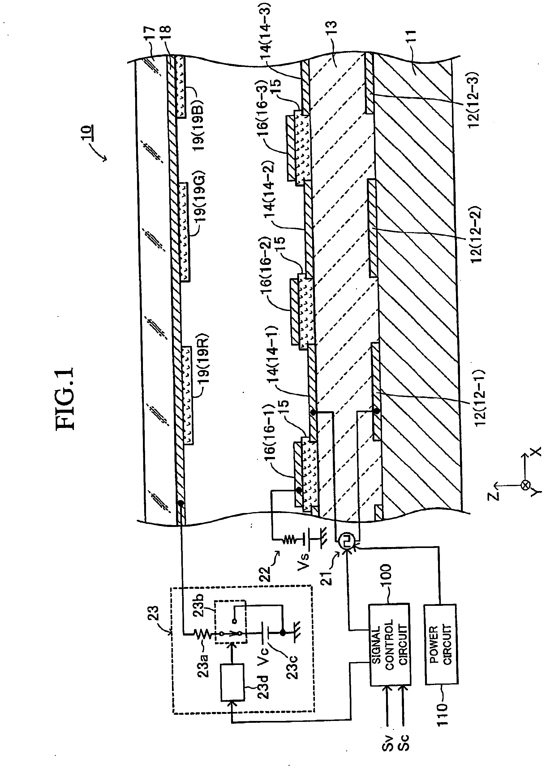
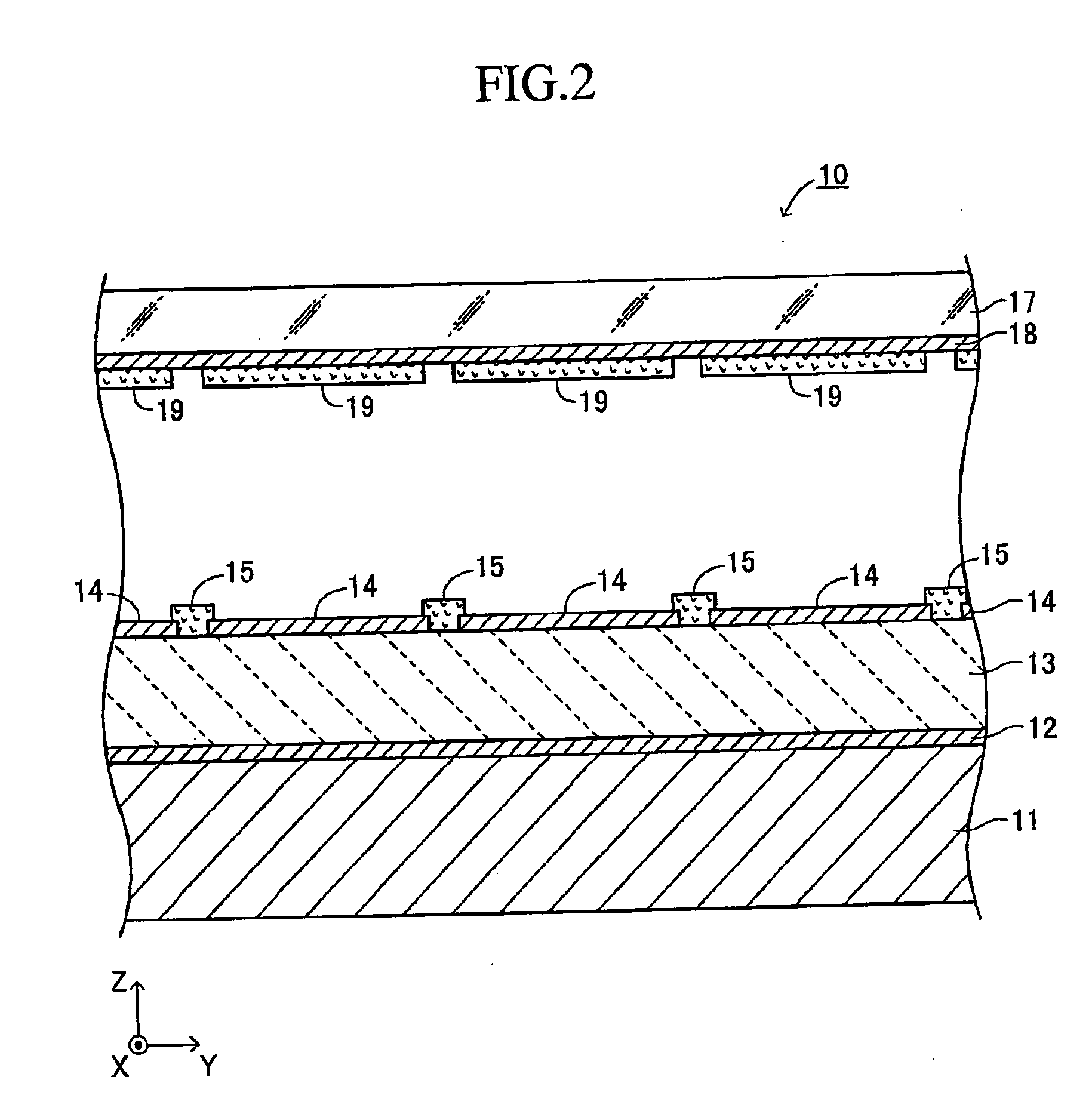
[0079] As shown in FIGS. 1 to 3, an electron emitting apparatus (an electron emitting device) 10 according to a first embodiment of the present invention includes a substrate 11, a plurality of lower electrodes (lower electrode layers) 12, an emitter section 13, a plurality of upper electrodes (upper electrode layers) 14, insulating layers 15, and focusing electrodes (focusing electrode layers, a bundling electrode to bundle emitted electrons) 16. FIG. 1 is a cross-sectional view of the electron emitting apparatus 10 taken along line I-I in FIG. 3, which is a partial plan view of the electron emitting apparatus 10. FIG. 2 is a cross-sectional view of the electron emitting apparatus 10 taken along line II-II in FIG. 3.
[0080] The substrate 11 is a thin plate having an upper surface and a lower surface parallel to the plane (X-Y plane) defined by the X axis and the Y axis perpendicular to each other. The thickness direction of the substrate 11 is the Z-axis direction perpen...
second embodiment
[0152] An electron-emitting apparatus according to a second embodiment of the present invention will now be described. The second embodiment differs from the first embodiment only in that the collector electrode ON time is set at a time point different from the collector electrode ON time of the first embodiment. Thus, the description below is mainly directed to this difference.
[0153] In the second embodiment, the collector electrode ON time is set at a fourth time point (4) (the time t11 represented by reference character B in FIG. 8) at which the interelectrode voltage (drive voltage) Vin is again set, after the electrons are emitted, at the positive predetermined voltage Vp. In detail, based on the signal fed from the signal control circuit 100, the collector voltage applying circuit 23 switches the switching point to which the fixed connection point of the switching element 23b is connected from the earthed switching point to the switching point connected to the constant voltag...
third embodiment
[0157] An electron-emitting apparatus according to a third embodiment of the present invention will now be described. The third embodiment differs from the first embodiment only in that the collector electrode ON time is set to a time point different from the collector electrode ON time of the first embodiment. Thus, the description below is mainly directed to this difference.
[0158] In the third embodiment, the collector electrode ON time is set at a particular time within the period “starting from immediately after a fifth time point (5) (i.e., a time t12 in FIG. 8) at which the inrush current in the emitter section 13 becomes the maximum by again changing the interelectrode voltage (drive voltage) Vin to the positive predetermined voltage Vp” after the electron emission and “ending at a sixth time point (6) (i.e., a time t14) at which the polarization reversal (the positive-side polarization reversal) in the emitter section is substantially completed”.
[0159] Specifically, the sw...
PUM
 Abstract
Description
Claims
Application Information
 - R&D
- Intellectual Property
- Life Sciences
- Materials
- Tech Scout
- Unparalleled Data Quality
- Higher Quality Content
- 60% Fewer Hallucinations
Browse by: Latest US Patents, China's latest patents, Technical Efficacy Thesaurus, Application Domain, Technology Topic, Popular Technical Reports.
© 2025 PatSnap. All rights reserved.Legal|Privacy policy|Modern Slavery Act Transparency Statement|Sitemap|About US| Contact US: help@patsnap.com


