Methods and apparatus providing double conversion/series-parallel hybrid operation in uninterruptible power supplies

Inactive Publication Date: 2006-06-08
CHEN HUEI JUNG
View PDF16 Cites 40 Cited by
  • Summary
  • Abstract
  • Description
  • Claims
  • Application Information

AI Technical Summary

Benefits of technology

[0016] To achieve these and other advantages and in accordance with the purpose of the present invention, as embodied and broadly described herein, a converter is employed to draw current from an AC power source and then deliver the current selectively to a DC bus or a load of the UPS; an inverter is employed to receive power from the DC bus and provide a regulated voltage to the load of the UPS. As the current is configured to deliver to the DC bus, the UPS is operated in a double conversion mode which features the VFI performance to respond to a drastic frequency disturbance from the AC power source; while the current is configured to deliver to the load, the UPS is operated in a series-parallel mode w

Problems solved by technology

However, though most double conversion UPS feature the VFI, the high power loss and poor efficiency resulted from their intrinsic series-series structures have inspired the inventions of new UPS structure; for example, an UPS structure according to U.S. Pat. No. 5686768, an UPS structure according to U.S. Pat. No. 6,744,648 and in FIG. 1, a structure also known as the Delta conversion UPS.
This causes the over current of the inverter or the shutdown of the converter.
In addition to the VI characteristic, the prior art series-parallel structures have other disadvantages; the Delta conversion UPS needs a bulky and expensive line frequency (60/50 HZ) transformer, shown as T1 in the FIG. 1; the structure of U.S. Pat. No. 5,687,768 needs no line frequency transformer but, in buck mode operations as in the FIG. 6 and the FIG. 8 of the specification of the patent, it generates discontinuous or pulsating current to the AC voltage source (utility power) causing severe elec

Method used


Image

  • Methods and apparatus providing double conversion/series-parallel hybrid operation in uninterruptible power supplies
  • Methods and apparatus providing double conversion/series-parallel hybrid operation in uninterruptible power supplies
  • Methods and apparatus providing double conversion/series-parallel hybrid operation in uninterruptible power supplies

Examples


Embodiment Construction

[0027] Reference will now be made in detail to the embodiments of the invention, examples of which are illustrated in the accompanying drawings. Reference in the specification to “one embodiment” or “an embodiment” means that a particular feature, structure, or characteristic described in connection with the embodiment is included in at least one embodiment of the invention. The appearances of the phrase “in one embodiment” in various places in the specification are not necessarily all referring to the same embodiment.

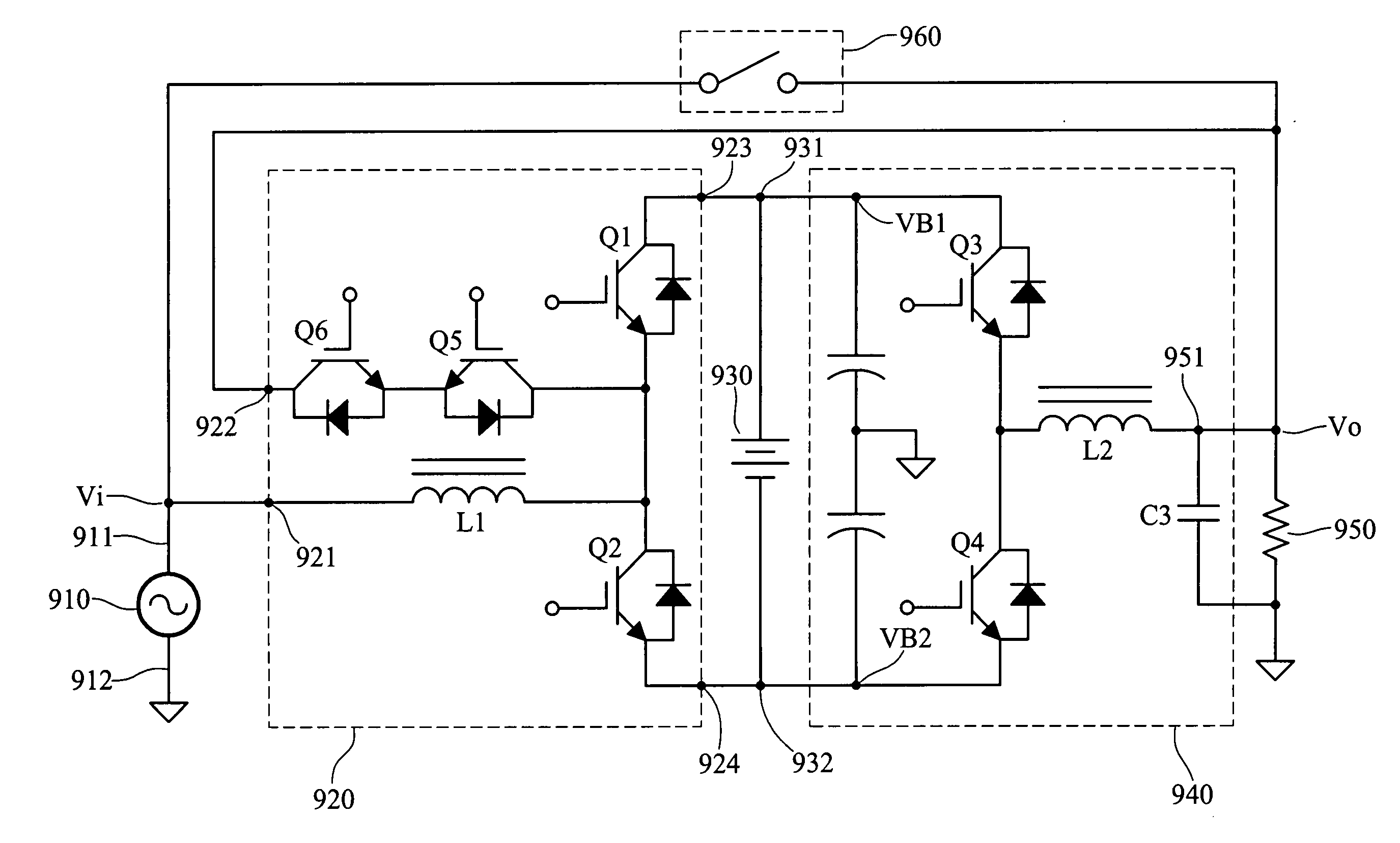
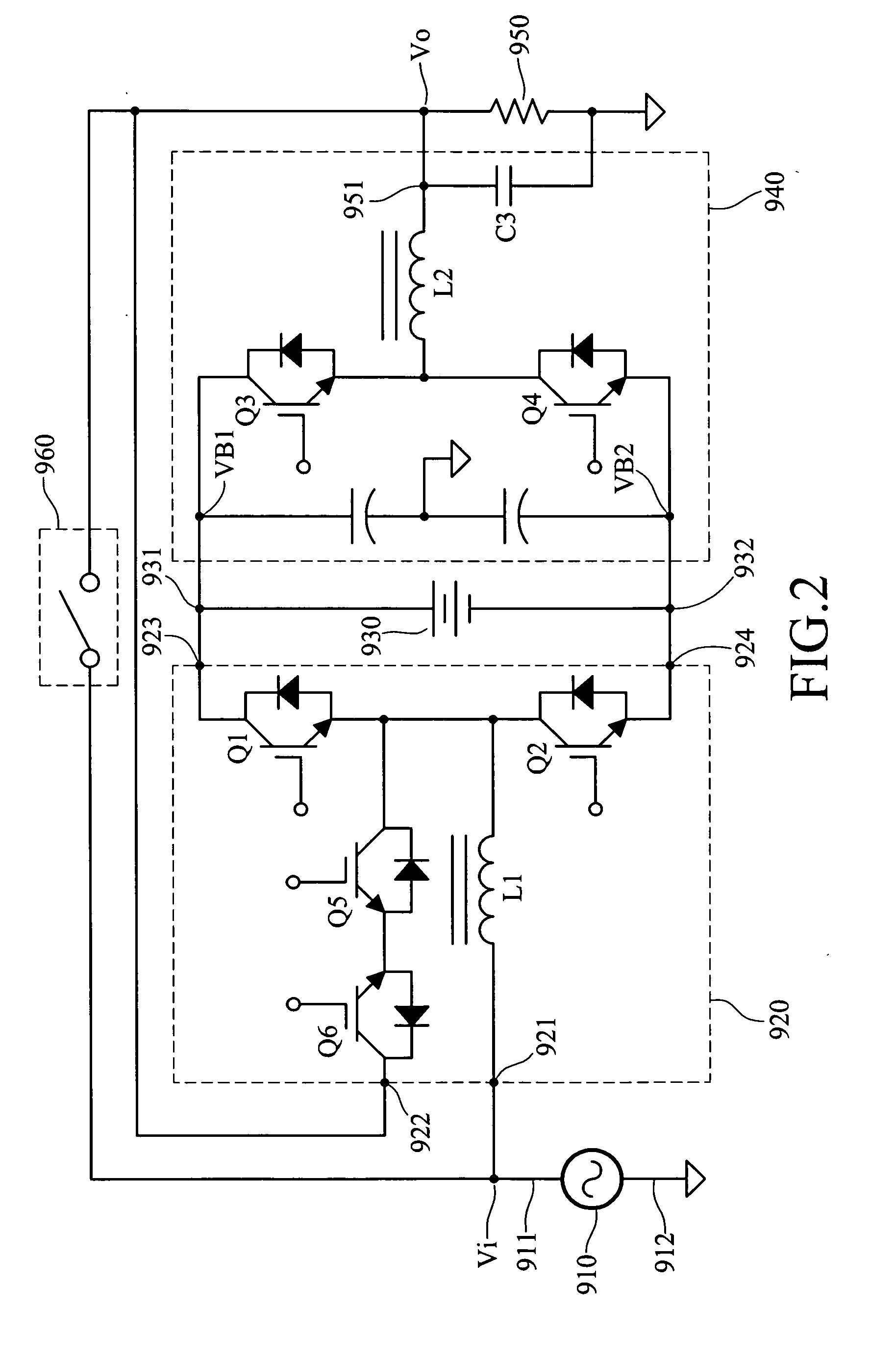
[0028]FIG. 2 illustrates an embodiment of an uninterruptible power supply (UPS) that can be configured to operate in a double conversion or a series-parallel mode according to the present invention.

[0029] The UPS comprises an input having a phase port 911 and a neutral port 912 for connecting to an AC power source 910, a converter 920, a DC power source 930 coupled to a DC bus comprising a first port 931, a second port 932 and a neutral port 912, an inverter 940, a o...


PUM


Abstract

An uninterruptible power supply (UPS) includes an AC power source, a DC power source coupled to a DC bus, a load, a converter, an inverter and a controller. Responsive to the controller, the inverter receives power from the DC bus to supply the load a regulated voltage; the converter, operated in a hybrid mode, receiving power from the AC power source to supply the DC bus a regulated DC voltage in a double conversion mode or to supply the power to the load in a series-parallel mode, or a combination of the two modes. In the stored energy mode, with an additional bypass switch, both the converter and inverter receive power from the DC power source and jointly supply the load a high quality voltage. These configurations improve the efficiency and enable the UPS readily meet the VFI and the high quality output voltage requirements per IEC62040-3.

Description

BACKGROUND OF THE INVENTION [0001] 1. Field of Invention [0002] The invention relates to power supplies, and more particularly to the structures and control method of uninterruptible power supplies. [0003] 2. Related Art [0004] Uninterruptible power supply systems have been widely used to protect electrical equipments from damages or failures caused by utility power disturbances. There are ten commonly recognized utility power disturbances; nine of the disturbances are voltage related and one of the disturbances is frequency related. [0005] International standard IEC62040-3 introduces a three step UPS classification code to standardize the UPS performance, which is briefly illustrated in “A New International UPS Classification by IEC 62040-3” (The 24′ International Telecommunication Energy Conference, 2002.) by Wilhelm Solter. IEC62040-3 STEP1 defines VFI (UPS output is independent of input supply voltage and frequency variations) as classification 1, leading the VI of classificatio...

Claims


Application Information

Patent Timeline
IPC IPC(8): H02J9/00
CPCH02J9/062
Inventor CHEN, HUEI-JUNG
Owner CHEN HUEI JUNG
Why Eureka
Try Eureka