
Apparatus and method for memory efficient, programmable, pattern matching finite state machine hardware

a finite state machine and pattern matching technology, applied in the field of integrated circuits, can solve the problems of sacrificing content delivery or network security, qos and signature-based security services finding it increasingly difficult to keep up with the demands of matching packet contents, and programmable fsms are often expensive, so as to reduce memory requirements and minimize the number of terms required

Inactive Publication Date: 2006-06-08
INTEL CORP +1
View PDF11 Cites 28 Cited by
  • Summary
  • Abstract
  • Description
  • Claims
  • Application Information

AI Technical Summary

Benefits of technology

[0012] The finite state machine that is implemented in hardware has significantly reduced memory requirements. The contents of both the content addressable memory and the static random memory is determined by an algorithm, in accordance with the present invention. The algorithm is an iterative algorithm which minimizes the number of terms required to represent the next-state transition functions. The data generated by this algorithm are subsequently uploaded to the two memories.

Problems solved by technology

As network speeds increase, QoS and signature-based security services are finding it increasingly more challenging to keep up with the demands of matching packet contents.
The services therefore sacrifice content delivery or network security by being required to miss packets.
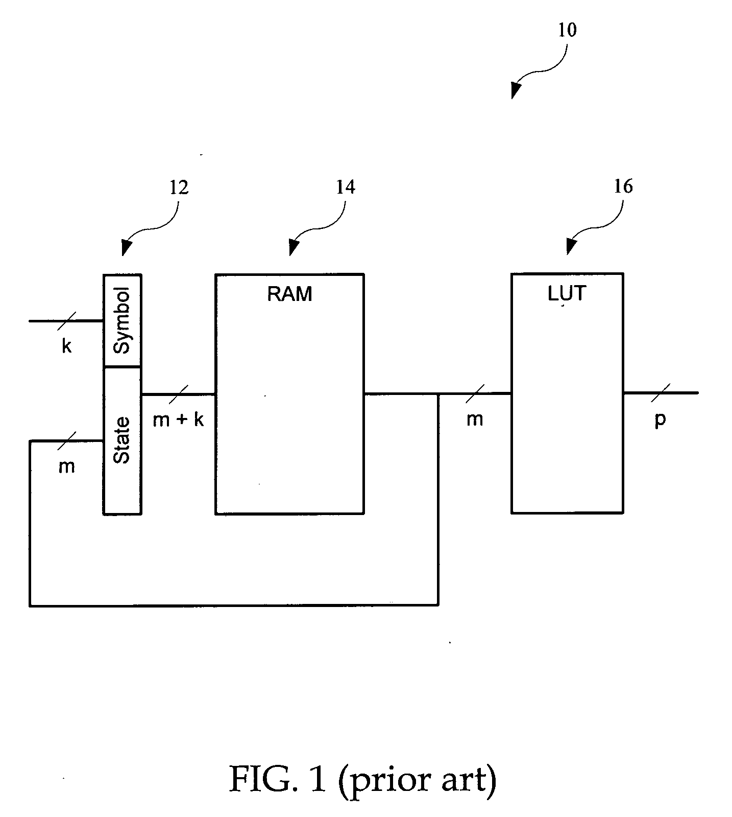
Programmable FSMs are often expensive because of the size of the memory required to store the transition table.
This problem is even more pronounced for fast FSMs which are required to compute the next state within a few and fixed number of clock cycles.
This poses a challenging task.
This technique also suffers from the problem that the stack memory is limited.

Method used


Image

  • Apparatus and method for memory efficient, programmable, pattern matching finite state machine hardware
  • Apparatus and method for memory efficient, programmable, pattern matching finite state machine hardware
  • Apparatus and method for memory efficient, programmable, pattern matching finite state machine hardware

Examples


Embodiment Construction

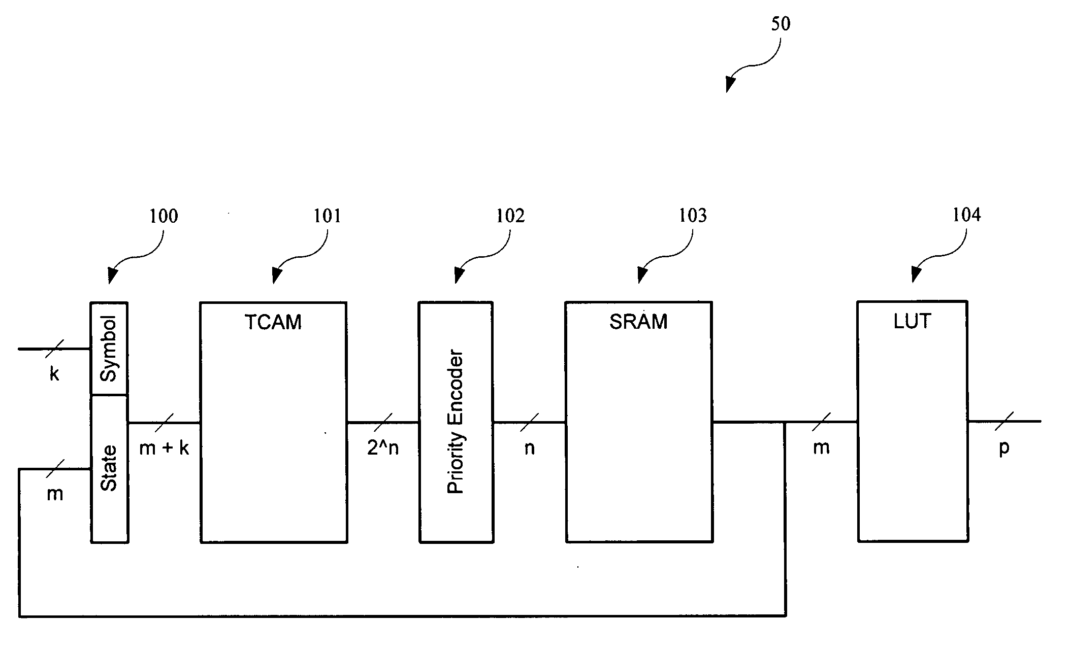
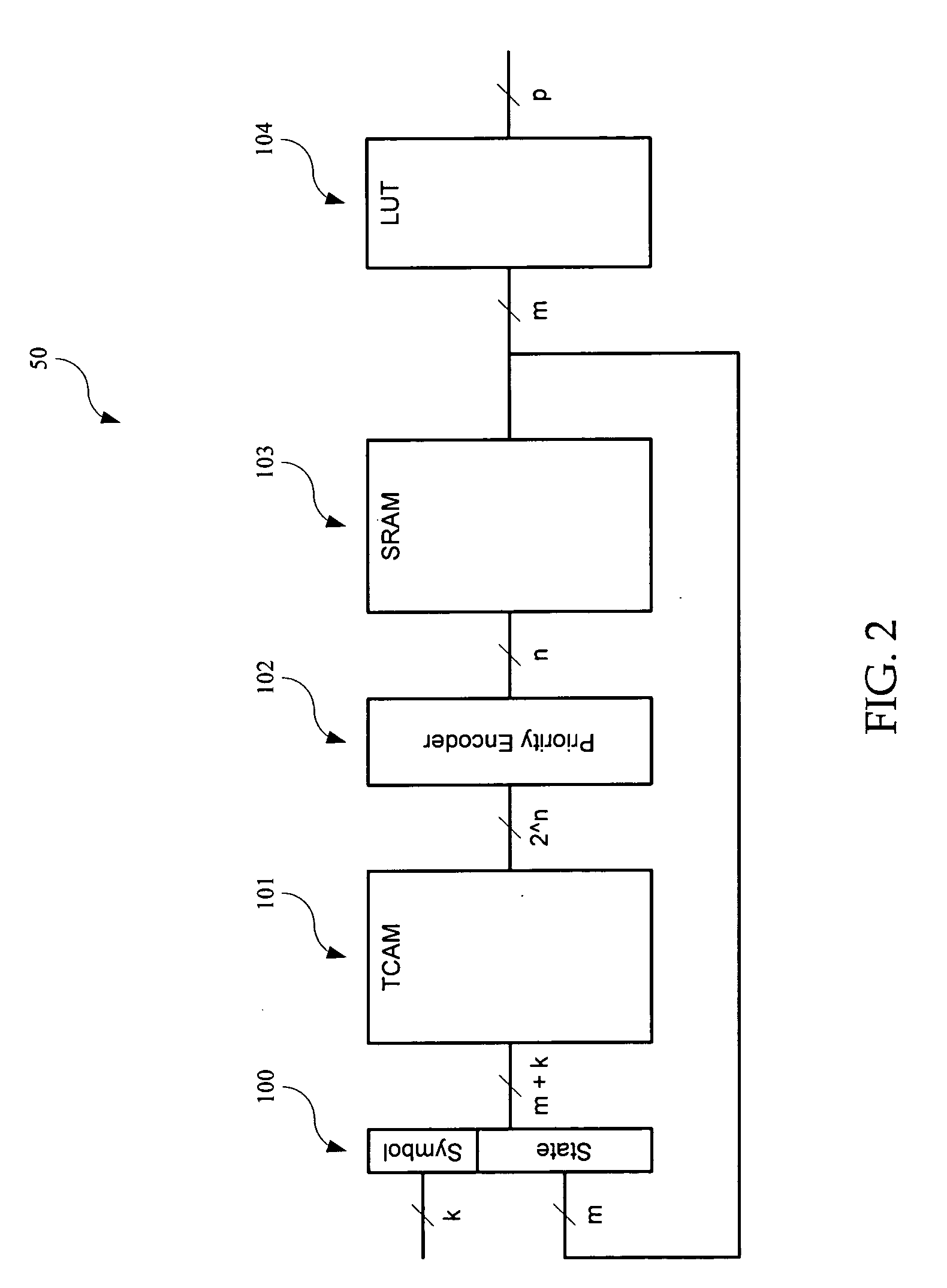
[0022] In accordance with the present invention, a programmable finite state machine (FSM), is configured to require less memory storage capacity to perform fast pattern matching than those known in the prior art. FIG. 2 is a simplified high-level block diagram of an FSM 50, in accordance with one embodiment of the present invention. FSM 50 is shown as including, in part, a register 100 adapted to store the current state and input symbol, a ternary content addressable memory (TCAM) 101 adapted to store transition rules, a priority encoder 102 adapted to select the most specific rule from all rules which match, an SRAM 103 adapted to deliver the next state in response to the rule selected by TCAM 101, and a look-up table (LUT) 104 adapted to deliver FSM 50's output defining the action the FSM 50 performs. Priority encoder 102 receives 2n wordlines (signals) and represents the first asserted wordline as an n-bit binary coded signal.

[0023]FIG. 3 is a simplified high-level block diagra...


PUM


Abstract

A programmable finite state machine (FSM) includes, in part, first and second memories, and a selection circuit coupled to each of the memories. Upon receiving a (k+m)-bit word representative of the k-bit input symbol and the m-bit current state, the first memory supplies one ore more matching transition rules stored therein. The selection circuit selects the most specific of the supplied rules. The transition rules are stored in the first memory in a ranking order of generality. The second memory receives the selected transition rule and supplies the next state of the FSM. The first memory may be a ternary content addressable memory and the second memory may be a static random access memory. The contents of both the content addressable memory and the static random memory is determined by an algorithm which minimizes the number of terms required to represent the next-state transition functions.

Description

CROSS-REFERENCES TO RELATED APPLICATIONS [0001] The present application claims benefit under 35 USC 119(e) of U.S. provisional application No. 60 / 454,398, filed on Mar. 12, 2003, entitled “Apparatus And Method For Memory Efficient, Programmable, Pattern Matching Finite State Machine Hardware”, the content of which is incorporated herein by reference in its entirety.FIELD OF THE INVENTION [0002] The present invention relates to integrated circuits, and more particularly to memory efficient programmable finite state machines. BACKGROUND OF THE INVENTION [0003] Deep content inspection of network packets is driven, in large part, by the need for high performance quality-of-service (QoS) and signature-based security systems. Typically QoS systems are configured to implement intelligent management and deliver content-based services which, in turn, involve high-speed inspection of packet payloads. Likewise, signature-based security services, such as intrusion detection, virus scanning, con...

Claims


Application Information

Patent Timeline
IPC IPC(8): G11C11/24G06FG06F7/02G06F12/00G06F21/00
CPCG06F7/02G06F21/554G06F21/567G06F2207/025G11C15/00H04L63/0227H04L63/12H04L63/1441
Inventor GOULD, STEPHENBARRIE, ROBERT MATTHEWWILLIAMS, DARRENDE JONG, NICHOLAS
Owner INTEL CORP
Learn More