Thermally tempered glass, and method and apparatus for manufacturing the glass

Inactive Publication Date: 2006-06-08
CENT GLASS CO LTD
View PDF4 Cites 19 Cited by
  • Summary
  • Abstract
  • Description
  • Claims
  • Application Information

AI Technical Summary

Benefits of technology

[0017] It was made possible by the present invention to stably produce thin-plate tempered glasses of thic

Problems solved by technology

In the case of producing thermally tempered glasses of thicknesses of 2.5 mm or less, particularly thin-plate tempered glasses of thicknesses of 2.3 mm or less, it is difficult to say that production processes of thermally tempered glasses are established by conventional methods of increasing glass temperature upon tempering and/or methods of obtaining large heat transfer coefficients.
Therefore, we are in a condition that desired thermally tempered glasses cannot be obtained.
However, a method of increasing the jetting speed from the nozzles or shortening the distance to the glass causes jetting marks of the nozzles on the glass, resulting in an optical problem.
By a method of enlarging the nozzle diameter or increasing the number of the nozzles, it is not possible to well manage the airflow after its impingement against glass, since the cross-sectional area occupied by the nozzles increases.
As a result, it is not possible

Method used


Image

  • Thermally tempered glass, and method and apparatus for manufacturing the glass
  • Thermally tempered glass, and method and apparatus for manufacturing the glass
  • Thermally tempered glass, and method and apparatus for manufacturing the glass

Examples


example 1

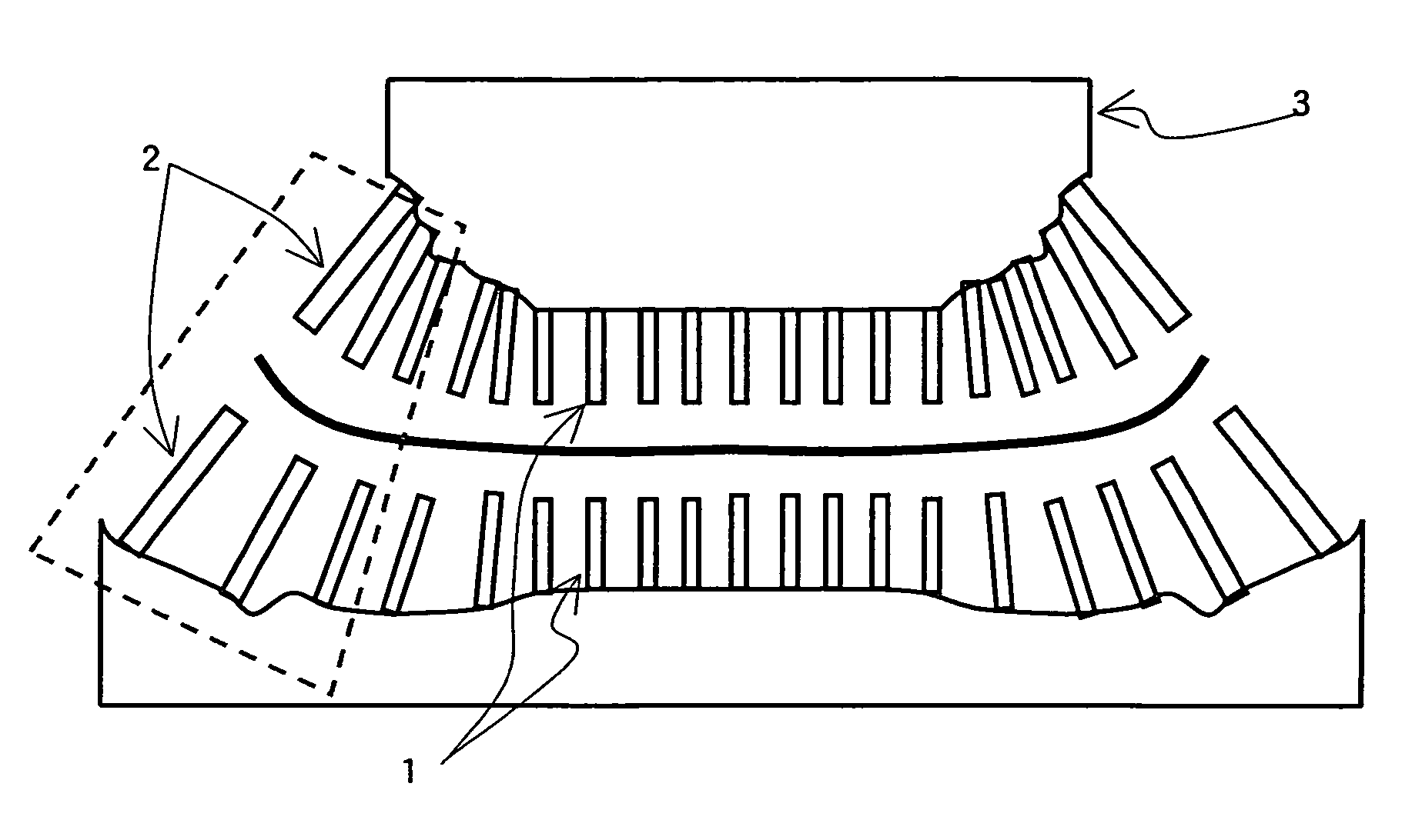
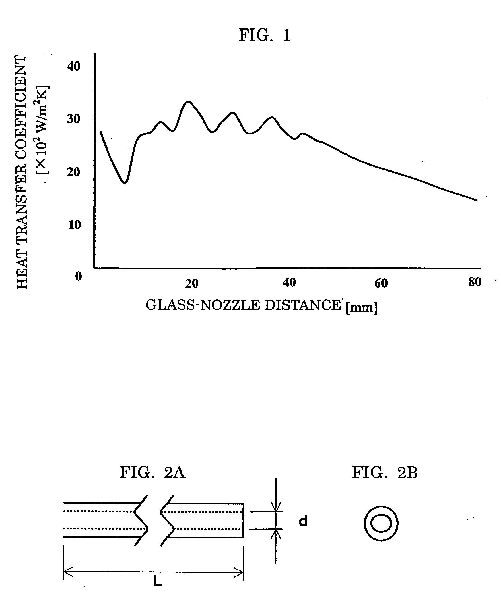
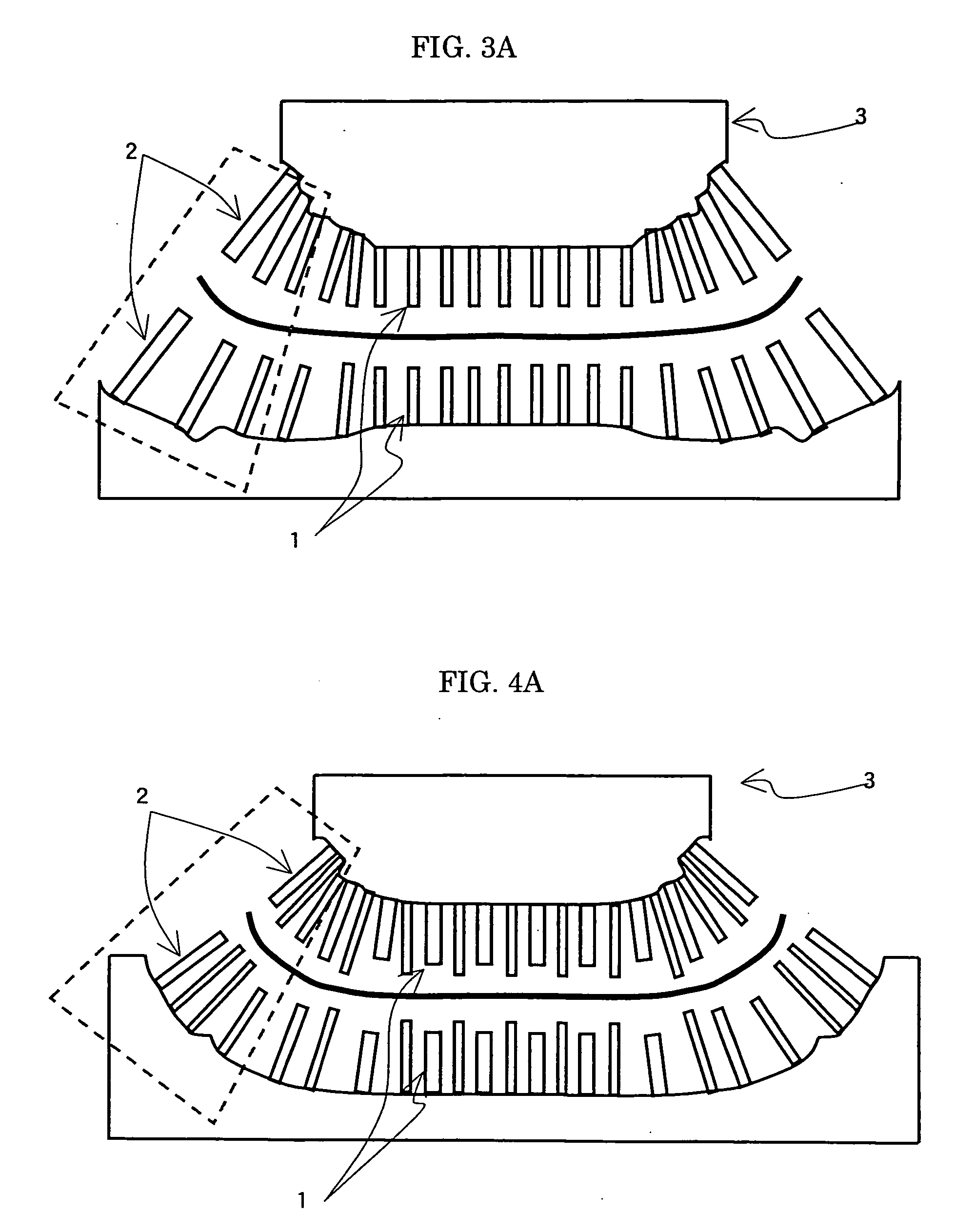
[0053] There was prepared a curved 2.3 mm thick glass having dimensions of 490×820 (mm). As shown in FIGS. 3A and 3B, a thermally tempered glass was produced by using a nozzle 1 group of a shape shown in FIGS. 2A and 2B having an inner diameter d of 3 mm and a length L of 100 mm for a relatively flat region forming portion and by using a nozzle 2 group of a shape shown in FIGS. 2A and 2B having an inner diameter d of 4 mm and a length L of 100-130 mm for a curved region forming portion (curved surface radius: ˜500 mm). Each nozzle communicates with a high-pressure air supply apparatus through a blast head 3. The distance between glass and nozzle upon this was based on about 30 mm, and the chamber pressure was adjusted to 0.4 mm.

[0054] As a result of an air-quench tempering treatment under this quenching condition, the fragment density (the number / 25 cm2) at the relatively flat region forming portion was about 100, and that even at the curved region forming portion was about 60. Thi...

example 2

[0055] There was prepared a curved 2.3 mm thick glass having dimensions of 490×820 (mm). A thermally tempered glass was produced by using a nozzle group having an inner diameter of 3 mm and a length of 100 mm for a relatively flat region forming portion and by using a nozzle group having an inner diameter of 4 mm and a length of 150-200 mm for a curved region forming portion (curved surface radius: ˜250 mm). The distance between glass and nozzle upon this was based on about 25 mm, and the chamber pressure was adjusted to 0.5 MPa.

[0056] As a result of an air-quench tempering treatment under this quenching condition, the fragment density (the number / 25 cm2) at the relatively flat region forming portion was about 350, and that even at the curved region forming portion was about 250. This result meets the specification as a tempered glass. When the surface compressive stress of this tempered glass was measured, it was 135 MPa at a place where the maximum value was obtained and 120 MPa ...

example 3

[0057] There was prepared a curved 2.3 mm thick glass having dimensions of 540×1150 (mm). A thermally tempered glass was produced by using a nozzle group having an inner diameter of 2.5 mm and a length of 100 mm for a relatively flat region forming portion, by using a nozzle group having an inner diameter 3 mm and a length of 150-200 mm for a curved region forming portion A (curved surface radius: ˜500 mm), and by using a nozzle group having an inner diameter of 4 mm and a length of 150-200 mm for a curved region forming portion B (curved surface radius: ˜250 mm). The distance between glass and nozzle upon this was based on about 25 mm, and the chamber pressure was adjusted to 0.55 MPa.

[0058] As a result of an air-quench tempering treatment under this quenching condition, the fragment density (the number / 25 cm2) at the relatively flat region forming portion was about 150, and that even at the curved region forming portion was about 80. This result meets the specification as a tempe...


PUM

PropertyMeasurementUnit
Lengthaaaaaaaaaa
Pressureaaaaaaaaaa
Pressureaaaaaaaaaa

Abstract

The invention relates, in case that a thermally tempered glass is produced by allowing an impact jet flow from quenching nozzles to blow against the glass, to a process for producing a curved shape, thermally tempered glass, characterized in that a quenching is conducted by simultaneously using at least two types of quenching nozzles having different exit diameters of the quenching nozzles. Furthermore, the invention relates to a curved, thermally tempered glass produced by this process and to an apparatus for producing the thermally tempered glass. In the invention, it is preferable that a exit diameter d is from φ1 mm to φ8 mm, a distance Z between the nozzle and the glass is 1 to 80 mm, a chamber pressure P is in a range of 0.1 to 0.8 MPa, and a heat flux difference is 150 kW/m2 or less. Furthermore, in the thermally tempered glass, it is preferable that a difference of surface compressive stress values within a glass surface is 20 MPa or less.

Description

BACKGROUND OF THE INVENTION [0001] The present invention relates to so-called thermally tempered glasses produced by air-quench method, particularly thermally-tempered curved glasses of thicknesses of 2.5 mm or less, their production process and their production apparatus. [0002] From the viewpoint of resource saving and energy saving, there is a progress to make thermally tempered glasses have thinner thicknesses and greater degrees of tempering. As means for this, chemical strengthening method and physical tempering method are mainly used. Chemical strengthening method is a method in which the glass surface is provided with a compressive stress by using ion exchange, crystallization, the difference in thermal expansion coefficient, etc., and tempered glasses by that method are called chemically strengthened glasses. Chemical strengthening method is suitable for strengthening thin plates having plate thicknesses of 3 mm or less, particularly 2 mm or less. Since the thickness of the...

Claims


Application Information

Patent Timeline
IPC IPC(8): C03B27/00B32B17/00C03B27/04C03B27/044
CPCC03B27/0404Y10T428/315C03B27/0445C03B27/0413
Inventor TAMAI, KOJITAKAYA, KAZUYOSHI
Owner CENT GLASS CO LTD
Why Eureka
Try Eureka