
Implantable medication delivery device

a medication delivery and implantable technology, applied in the direction of instruments, process and machine control, etc., can solve the problems of inacceptable medication discharge, and achieve the effects of reducing pump size and energy requirements, high space efficiency, and safe delivery of controlled medication doses

Active Publication Date: 2006-06-08
MEDTRONIC MIMIMED INC
View PDF10 Cites 34 Cited by
  • Summary
  • Abstract
  • Description
  • Claims
  • Application Information

AI Technical Summary

Benefits of technology

[0004] The present invention is directed to a medication delivery device comprising an ambient reservoir and housing integrated so as to be highly space efficient for reliably and safely delivering controlled medication doses to a target body site. Devices in accordance with the invention include a mounting structure for supporting a reservoir peripheral wall which includes a movable, e.g., flexible, portion. The reservoir wall has an outer surface exposed to an ambient pressure (equal to the pressure at the tip of an output catheter) which establishes the same pressure within the reservoir interior volume. As a consequence of the reservoir and catheter tip being at the same pressure, the pump size and energy requirements are reduced as compared to the aforementioned exemplary prior art systems.
[0007] In accordance with an alternative and / or additional feature for preventing medication flowthrough, a protective substantially rigid shell is mounted around the reservoir wall to prevent the inadvertent application of a force thereto. In order to maintain ambient pressure in the reservoir, the shell is configured to allow body fluid to enter and exit the shell to enable the reservoir to expand (when being filled with medication) and contract (as medication is being discharged). In accordance with a second preferred embodiment, the shell includes a diffusive membrane (e.g., cellulose acetate membrane) that permits body fluid to flow slowly into the shell interior volume but prevents undesirable tissue growth therein. The shell preferably also includes a check valve which permits relatively rapid fluid outflow to permit the reservoir to fill and expand within the shell interior volume.

Problems solved by technology

More particularly, it is unacceptable for medication to be discharged as a result of the reservoir wall being pressed, e.g., as a consequence of the patient being bumped.

Method used


Image

  • Implantable medication delivery device
  • Implantable medication delivery device
  • Implantable medication delivery device

Examples


Embodiment Construction

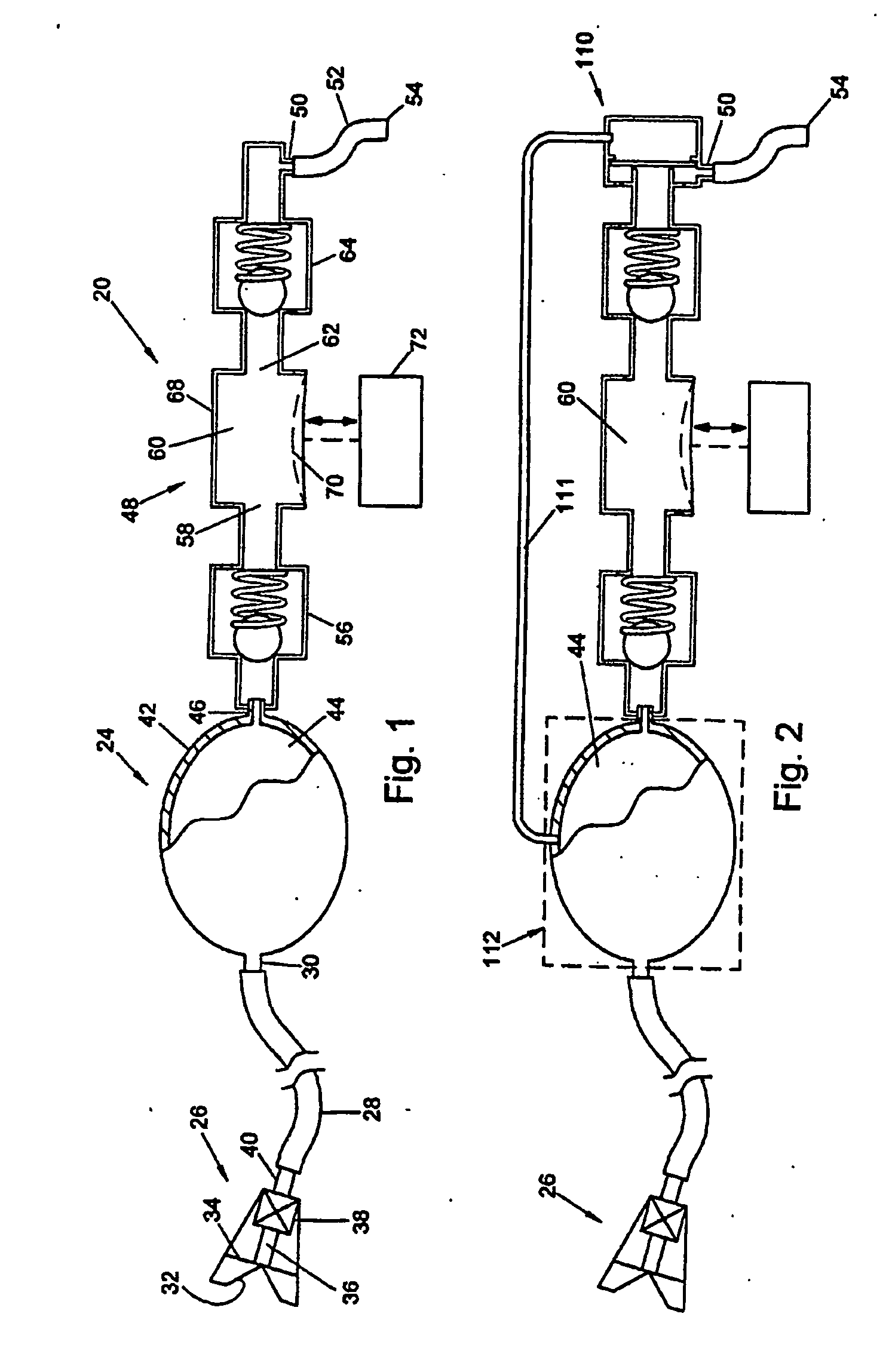
[0021] Attention is initially directed to FIG. 1 which schematically depicts an implantable medication delivery system 20 including a variable volume reservoir 24 for storing medication. The reservoir 24 is preferably refillable, e.g., via a fill device 26 and tube 28 coupled to a reservoir fill port 30. The fill device 26 preferably defines a conical entrance 32 for guiding the needle of a syringe (not shown) through a self healing septum 34 to a channel 36 and check valve 38. The outlet of check valve 38 is coupled via nipple 40 to the upstream end of tube 28. The downstream end of tube 28 is coupled to the reservoir fill port 30.

[0022] The variable volume reservoir 24 is comprised of a wall 42 including at least a portion supported for movement to enable the reservoir interior volume 44 to expand and contract. Although the reservoir 24 is most simply formed of flexible, or flaccid, nonextensible nonporous material forming a sack, it can also be provided in various alternative co...


PUM


Abstract

An implantable medication delivery device that is highly space efficient and can reliably and safely deliver controlled medication doses to a target site. The system includes a variable volume medication reservoir that is exposed to an ambient pressure equal to the ambient pressure at a system outlet port. A pump / valve subassembly is provided to draw medication from the reservoir and force a medication dose along a fluid transfer passageway to the outlet port. The pump / valve subassembly incorporates a safety mechanism, e.g., a balanced valve, which normally blocks medication flow to the outlet port and opens only in response to a pump induced unbalancing force. A protective shell is also disclosed for protecting the ambient reservoir.

Description

RELATED APPLICATIONS [0001] This application claims the benefit of U.S. Application 60 / 383,237 filed on 22 May 2002.FIELD OF THE INVENTION [0002] The present invention is directed to implantable medication delivery devices useful for delivering prescribed medication doses to targeted body sites. BACKGROUND OF THE INVENTION [0003] Commercially available implantable medication delivery devices are exemplified by a Synchromed product marketed by Medtronic (of Minneapolis, Minn., USA) and a MIP product manufactured by Minimed, now a division of Medtronic. Both of these devices employ a medication reservoir comprising a bellows that contracts as medication is extracted by a pump mechanism. The reservoir volume change is accommodated by a second chamber which contains a propellant such as Freon in a gas / liquid equilibrium. The propellant functions to maintain a constant absolute pressure at body temperature. In the case of the MIP product, the propellant is a liquid at body temperature cr...

Claims


Application Information

Patent Timeline
Patent Type & Authority Applications(United States)
IPC IPC(8): A61K9/22A61B19/00A61MA61M1/00A61M5/142A61M5/168A61M37/00A61M39/02
CPCA61M5/14224A61M5/14276A61M39/0208A61M2005/14264A61M2039/242A61M2210/0693
Inventor LORD, PETER C.NASON, CLYDE K.YAP, DARREN Y.K.DAS, STEPHEN D.LEBEL, RONALD J.
Owner MEDTRONIC MIMIMED INC
Learn More