Bone treatment systems and methods

Active Publication Date: 2006-06-08
DFINE INC
View PDF99 Cites 122 Cited by
  • Summary
  • Abstract
  • Description
  • Claims
  • Application Information

AI Technical Summary

Benefits of technology

[0018] Certain embodiments of the invention provide systems and methods for utilizing Rf energy in combination with a bone fill material that carries an electrically conductive filler for polymerizing surface portions of the inflow plume to thereby control the

Problems solved by technology

Medical advances aimed at slowing or arresting bone loss from aging have not provided solutions to this problem.
Osteoporosis affects the entire skeleton but most commonly causes fractures in the spine and hip.
Spinal or vertebral fractures also cause other serious side effects, with patients suffering from loss of height, deformity and persistent pain which can significantly impair mobility and quality of life.
Osteoporosis describes a condition of decreased bone mass that leads to fragile bones which are at an increased risk for fractures.
In an osteoporosis bone, the sponge-like cancellous bone has pores or voids that increase in dimension making the bone very fragile.
In an elderly patient, bone resorption can surpass bone formation thus resulting in deterioration of bone density.
Since the PMMA needs to be is forced into the cancellous bone, the techniques require high pressures and fairly low viscosity cement.
Since the cortical bone of the targeted vertebra may have a recent fracture, there is the potential of PMMA leakage.
Leakage of PMMA during vertebroplasty can result in very serious complications including compression of adjacent structures that necessitate emergency decompressive surgery.
The exothermic reaction of PMMA carries potential catastrophic consequences if thermal damage were to extend to the dural sac, cord, and nerve roots.
Vertebroplasty patients

Method used


Image

  • Bone treatment systems and methods
  • Bone treatment systems and methods
  • Bone treatment systems and methods

Examples


Example

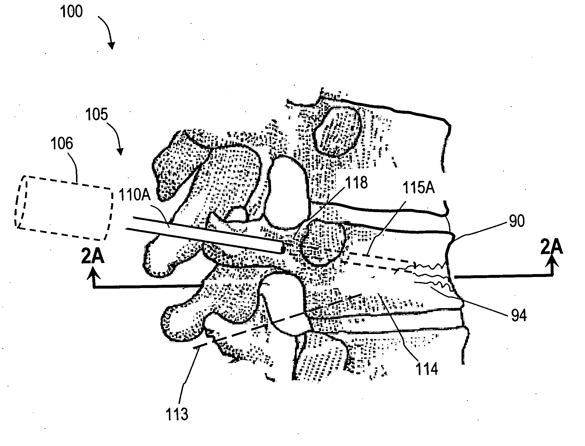
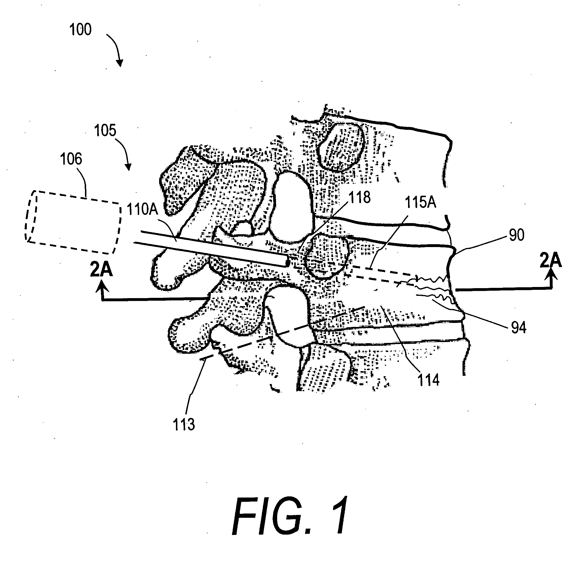
[0052]FIG. 1 illustrates one embodiment of the invention in treating a spine segment in which a vertebral body 90 has a wedge compression fracture indicated at 94. In one embodiment, the systems and methods of the invention are directed to safely introducing a bone fill material into cancellous bone of the vertebra without extravasion of fill material in unwanted directions (i) to prevent micromotion in the fracture for eliminating pain, and (ii) to support the vertebra and increase vertebral body height. Further, the invention includes systems and methods for sealing cancellous bone (e.g., blood vessels, fatty tissues etc.) in order to prevent monomers, fat, fill material and other emboli from entering the venous system during treatment.

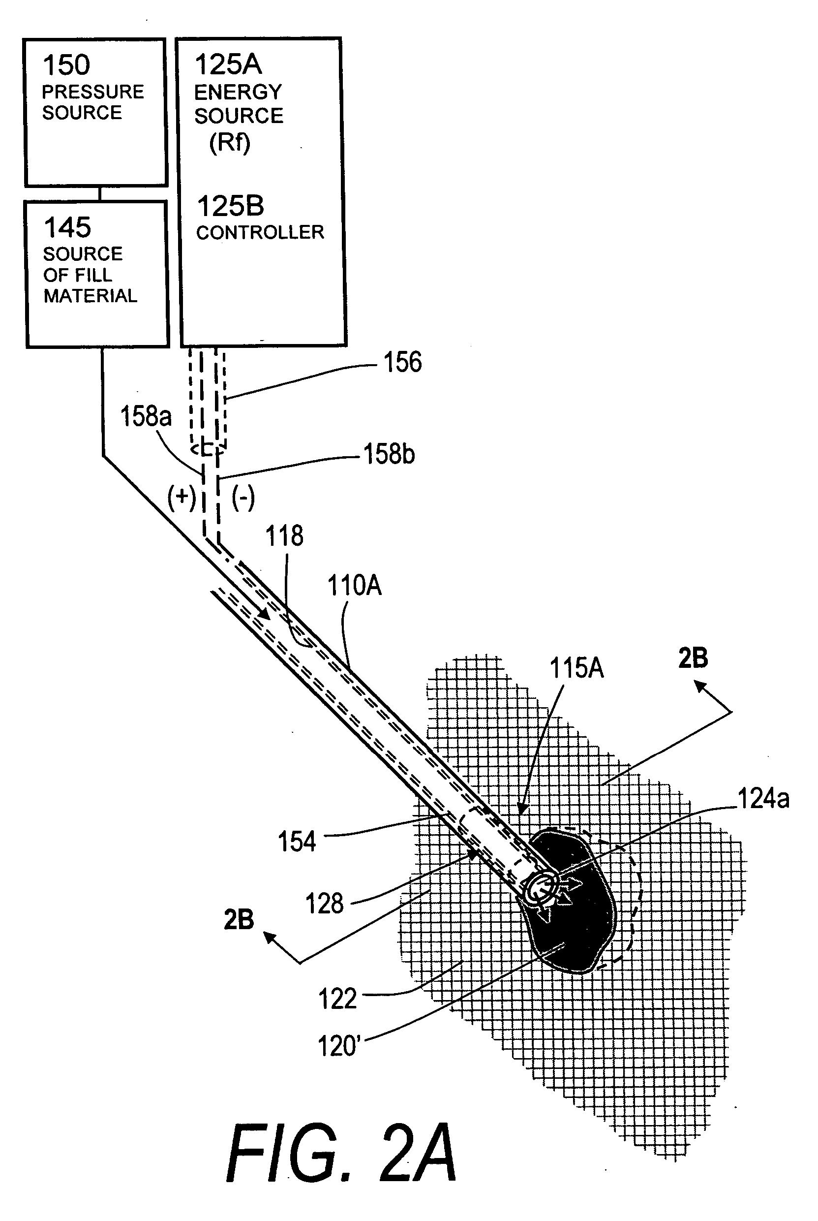
[0053]FIG. 1 illustrates a fractured vertebra and bone infill system 100 which includes probe 105 having a handle end 106 extending to an elongated introducer 110A and working end 115A, shown in FIG. 2A. The introducer is shown introduced through p...


PUM


Abstract

The present invention relates in certain embodiments to medical devices for treating osteoplasty procedures such as vertebral compression fractures. More particularly, embodiments of the invention relate to instruments and methods for controllably restoring vertebral body height by controlling the geometry of fill material introduced into cancellous bone. An exemplary system utilizes Rf energy in combination a conductive bone fill material for polymerizing the surface of the inflow plume to control the geometry of the fill material and the application of force caused by inflows of fill material. In another embodiment, method of treating bone includes injecting a volume of fill material into a bone and selectively modifying a viscosity of a selected portion of the bone filler to control the direction of flow of the fill material within the bone. A system for treating bone using this method includes an introducer for delivering fill material into the bone and an energy source selectively coupleable to the fill material to alter the viscosity of the fill material as it flows out of the introducer.

Description

CROSS-REFERENCE TO RELATED APPLICATIONS [0001] This application claims the benefit of Provisional U.S. Patent Application Ser. No. 60 / 633,509 filed Dec. 6, 2004, titled Bone Fill Materials and Methods of Use for Treating Vertebral Fractures the entire contents of which are incorporated herein by reference and should be considered a part of this specification. This application is also related to U.S. patent application Ser. No. ______ (Atty. Docket No. DFINE.001A1), filed Jun. 24, 2005, titled Bone Treatment Systems and Methods, the entire contents of which are hereby incorporated by reference and should be considered a part of this specification.BACKGROUND OF THE INVENTION [0002] 1. Field of the Invention [0003] The present invention relates in certain embodiments to medical devices for treating osteoplasty procedures such as vertebral compression fractures. More particularly, embodiments of the invention relate to instruments and methods for controllably restoring vertebral body he...

Claims


Application Information

Patent Timeline
IPC IPC(8): A61F2/34
CPCA61B17/7095A61B17/7098A61B17/864A61B17/8811A61B17/8836A61B2017/00022A61B2017/00026A61B2017/00084A61F2/44
Inventor TRUCKAI, CSABASHADDUCK, JOHN H.LUZZI, ROBERTCARLSON, GRACE A.RAPPLEYE, C. TRAVIS
Owner DFINE INC
Why Eureka
Try Eureka