
Turbo charged diesel-type piston engine and method for controlling such an engine

a technology of turbocharged diesel and piston engine, which is applied in the direction of electric control, liquid fuel engine, machines/engines, etc., can solve the problems of reducing reducing the temperature at combustion, and increasing the back-pressure of the exhaust gas, so as to increase the thermal efficiency of the internal combustion engin

Inactive Publication Date: 2006-06-15
VOLVO LASTVAGNAR AB
View PDF28 Cites 27 Cited by
  • Summary
  • Abstract
  • Description
  • Claims
  • Application Information

AI Technical Summary

Benefits of technology

[0007] An object of the invention is to provide a method for controlling an internal combustion engine, by which the thermal efficiency of the internal combustion engine can be increased while the requirements relating to nitrogen oxide and soot particle emissions continue to be maintained.

Problems solved by technology

Reducing the temperature at combustion, however, creates problems.
In certain operating conditions, the quantity of soot particles increases, which can result in an engine, for this reason, failing to win approval under prevailing emissions legislation.
Moreover, the thermal efficiency of the internal combustion engine may diminish when the temperature falls.
The presence of catalytic reaction chambers raises, however, the exhaust-gas back-pressure.
An increased exhaust-gas back-pressure causes a fall in the thermal efficiency of the internal combustion engine.
Particle traps also give rise to increased exhaust back-pressure and hence lower thermal efficiency for the internal combustion engine.
One problem facing manufacturers of internal combustion engines on which statutory requirements are imposed with respect of maximally permitted emission levels of soot particles and nitrogen oxide compounds lies in the fact that the required permitted emission levels are constantly being lowered.
Demands for reduced emission levels mean, firstly, that the engine cannot be optimized for low fuel consumption and, secondly, that emission-reducing peripheral equipment is called for which contributes to reduced thermal efficiency for the internal combustion engine.

Method used


Image

  • Turbo charged diesel-type piston engine and method for controlling such an engine
  • Turbo charged diesel-type piston engine and method for controlling such an engine
  • Turbo charged diesel-type piston engine and method for controlling such an engine

Examples


Embodiment Construction

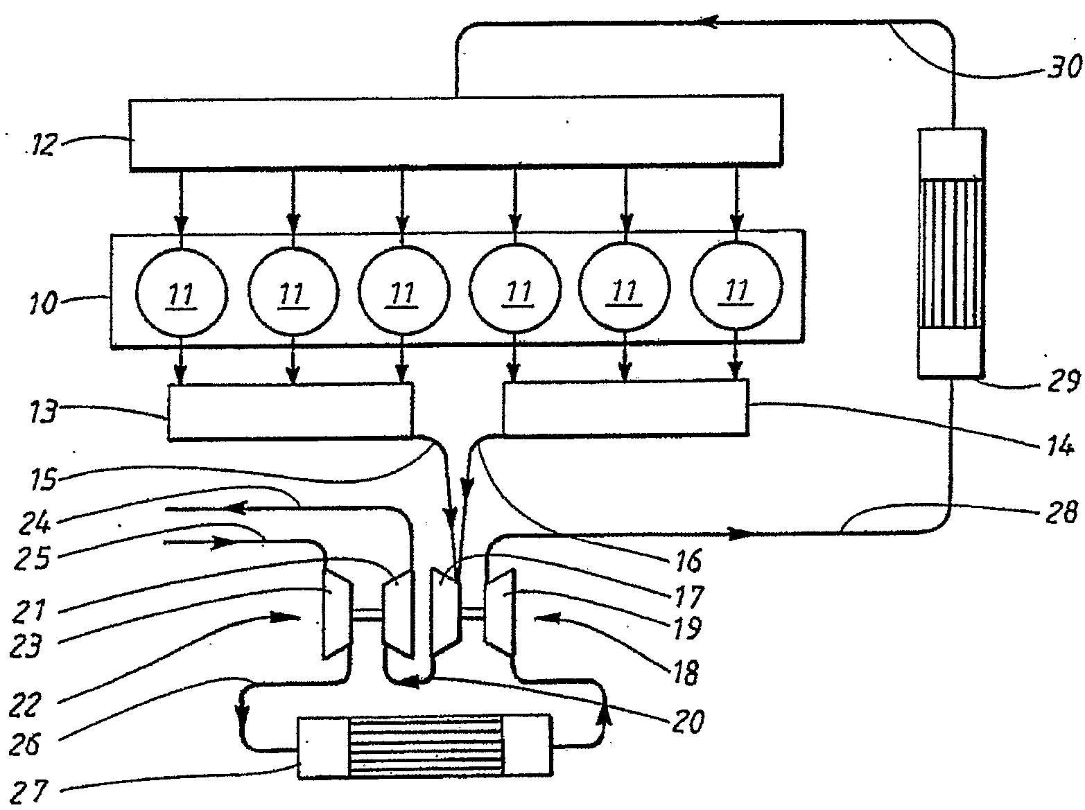
[0064]FIG. 16 represents diagrammatically an internal combustion engine controlled to obtain good thermal efficiency. The internal combustion engine 51 is of the piston engine type and comprises a set of combustion chambers, each formed by a cylinder 52, a movably arranged piston 53 in each cylinder, which piston is connected to a crankshaft 54 by a connecting rod 55. The combustion chamber is fitted with an injection device 56 designed to inject fuel directly into the combustion chamber. The injection device is designed to provide a specific injection time less than 0.12 crank angle degrees / (bar×m / s) within an operating range for the internal combustion engine at a mean piston velocity greater than 6 m / s at an engine load greater than 6 bar BMEP.

[0065] To this end, the injection device comprises an injection nozzle allowing a specific injection time less than 0.12 crank angle degrees / (bar×m / s). For an internal combustion engine with a cubic capacity of 21 / cylinder, a sprayer with ...


PUM


Abstract

A piston engine and a method for controlling a diesel-type piston engine including at least one combustion chamber formed by a cylinder, a movably arranged piston in each cylinder, which piston is connected to a crankshaft, an injection device designed to inject fuel directly into the combustion chamber and turbo system comprising a low pressure turbo and a high pressure turbo. The thermal efficiency of the internal combustion is increased while requirements relating to nitrogen oxide and soot particle emissions continue to be maintained.

Description

CROSS-REFERENCE TO RELATED APPLICATIONS [0001] The present application is a continuation patent application of International Application No. PCT / SE2004 / 000752 filed 14 May 2004 and International Application No. PCT / SE2004 / 000715 filed 11 May 2004, both of which were published in English pursuant to Article 21(2) of the Patent Cooperation Treaty, and both of which claim priority to Swedish Application No. 0301412-3 filed 15 May 2003. Said applications are expressly incorporated herein by reference in their entireties. TECHNICAL FIELD [0002] The present invention relates to a method for controlling a piston engine. Particularly, it relates to a method for controlling a diesel-type internal combustion engine in which fuel is injected directly into the combustion chambers for ignition. BACKGROUND OF THE INVENTION [0003] In a standard direct-injection diesel engine for heavy goods vehicles, i.e. a diesel engine with a cubic capacity between 0.5 and 4 liters per cylinder, the engine is co...

Claims


Application Information

Patent Timeline
IPC IPC(8): F02B33/42F02B3/08F01D5/04F01N13/14F02B3/06F02B23/06F02B29/04F02B37/00F02B37/013F02B37/02F02B41/10F02D41/00F02D41/40F02M25/07F04D29/28
CPCF01D5/048F01N13/107F02B3/06F02B23/0672F02B29/0412F02B29/0418F02B29/0425F02B29/0493F02B37/00F02B37/013F02B37/02F02B37/025F02B41/10F02B2275/14F02D41/40F02D2041/001F02M25/0707F02M25/0711F02M25/0727F02M25/0738F04D29/284Y02T10/125Y02T10/146Y02T10/44Y02T10/123Y02T10/144Y02T10/163F02B37/004F05D2220/40F02M26/05F02M26/08F02M26/23F02M26/33Y02T10/12Y02T10/40
Inventor GOBERT, ULRICHGRUNDITZ, DANIELKRAUSCHE, SEBASTIAN
Owner VOLVO LASTVAGNAR AB
Learn More