Freezer

Inactive Publication Date: 2006-06-15
DAIKIN IND LTD
View PDF12 Cites 21 Cited by
  • Summary
  • Abstract
  • Description
  • Claims
  • Application Information

AI Technical Summary

Benefits of technology

[0039] In accordance with the first invention, the liquid seal mechanism (37), (39, SV7), (40, SV8), (90), (21) is provided so that a side short of the expansion mechanism (46, 52) between the second utilization-side heat exchanger (41) and the first utilization-side heat exchanger (45, 51) is held in a full liquid state during the 100 percent heat recovery operation mode. In other words, liquid refrigerant is inhibited from flowing towards the main flow pipe (11) and the liquid pipe (10) from the second branch pipe (11b) at flow rates more than necessary. As a result, the rate of flow of the refrigerant being supplied to the first utilization-side heat exchanger (45, 51) is secured at satisfactory levels. Therefore, even when outside air temperatures are low, it is possible to prevent the capability to provide refrigeration from degrading during the 100 percent heat recovery operation mode.
[0040] In accordance with the second invention, the backflow prevention mechanism (37) is provided so that refrigerant is inhibited from flowing towards the main flow pipe (11) and the liquid pipe (10) during the 100 percent heat recovery operation mode. Such arrangement provides stable refrigerant flow during the 100 percent heat recovery operation mode. Therefore, even when outside air temperatures are low, it is possible to prevent the capability to provide refrigeration from degrading during the 100 percent heat recovery operation mode.
[0041] In accordance with the third invention, even when the temperature of outside air falls during the 100 percent heat recovery operation mode, no refrigerant enters the receiver (14) and the rate of flow of the refrigerant in the first utilization-side heat exchanger (45, 51) will not become insufficient. Therefore, even in the case where the receiver (14) is provided in the refrigerant circuit, it is possible to prevent the capability to pro

Problems solved by technology

This complicates the work of pipe connection, and there

Method used


Image

  • Freezer
  • Freezer
  • Freezer

Examples


Example

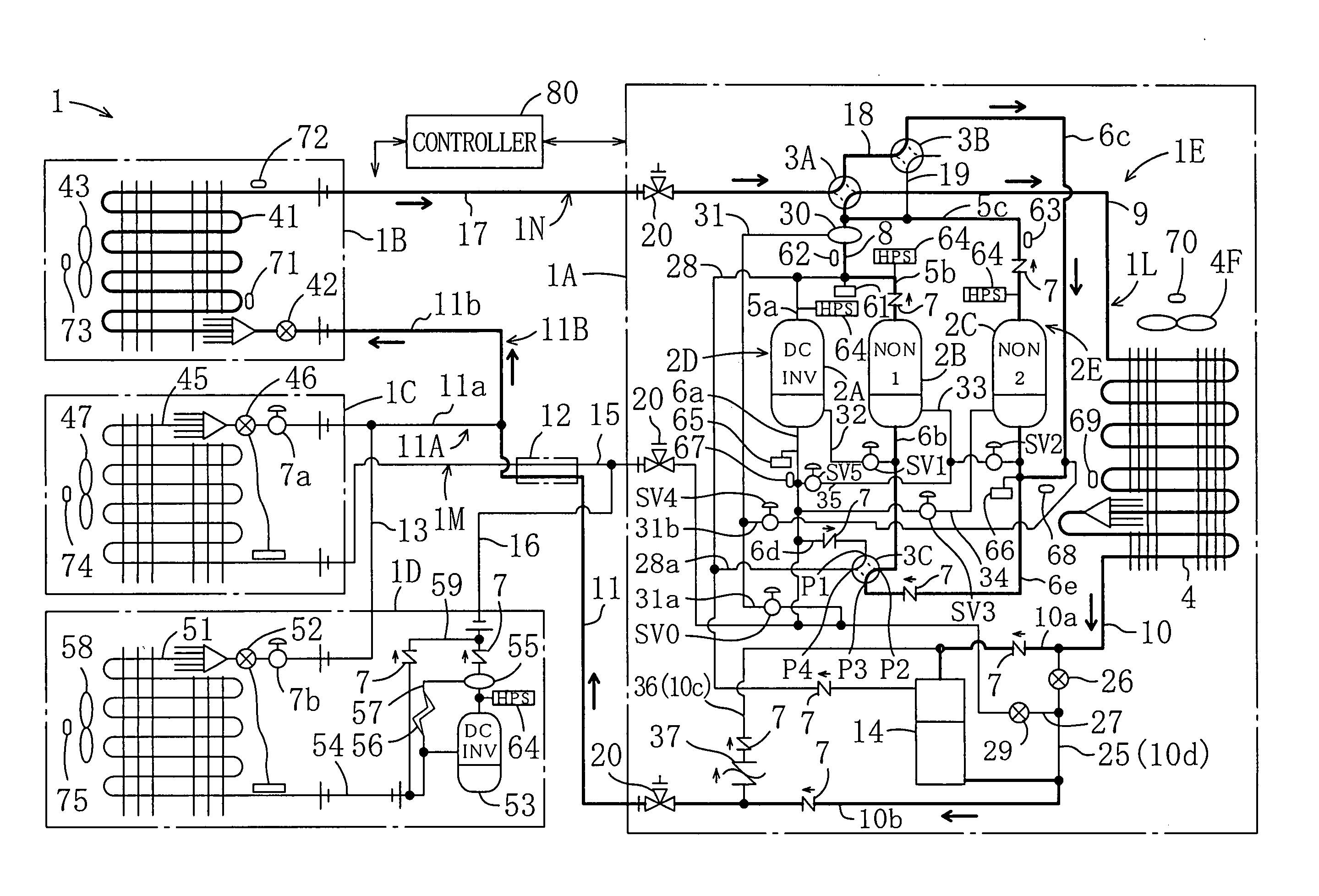
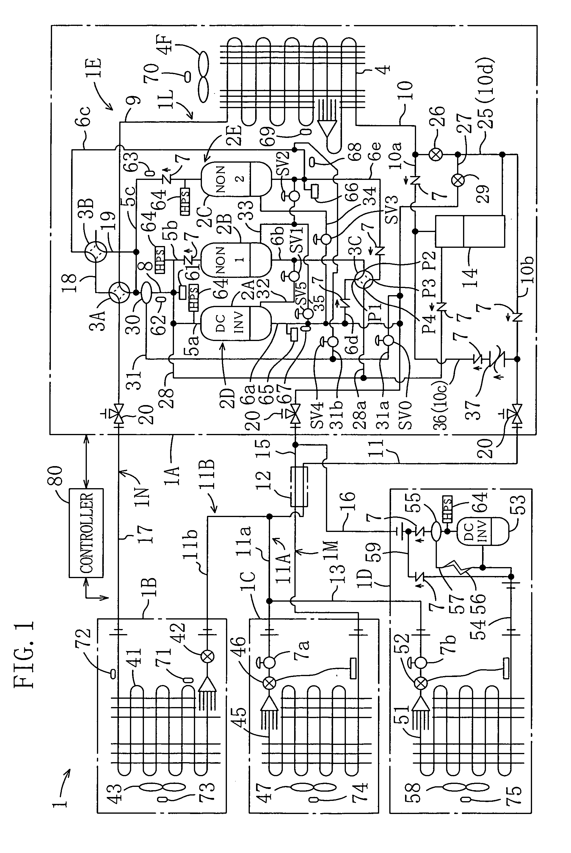
[0080] As shown FIG. 1, a refrigeration apparatus (1) according to a first embodiment of the present invention is intended for installation in a convenience store or the like for providing cold-storage showcase refrigeration, freeze-storage showcase refrigeration, and space heating / cooling in the shop.

[0081] The refrigeration apparatus (1) of the first embodiment includes an outdoor unit (1A), an indoor unit (1B), a cold storage unit (1C), and a freeze storage unit (1D), and is provided with a refrigerant circuit (1E) which performs a vapor compression refrigeration cycle. The refrigerant circuit (1E) is provided with a first system-side circuit for cold storage and freeze storage, and a second system-side circuit for air conditioning. The refrigerant circuit (1E) is configured so as to be switchable between a cooling cycle and a heating cycle.

[0082] The indoor unit (1B) is configured so that it selectively performs a space cooling operation mode or a space heating operation mode,...

Example

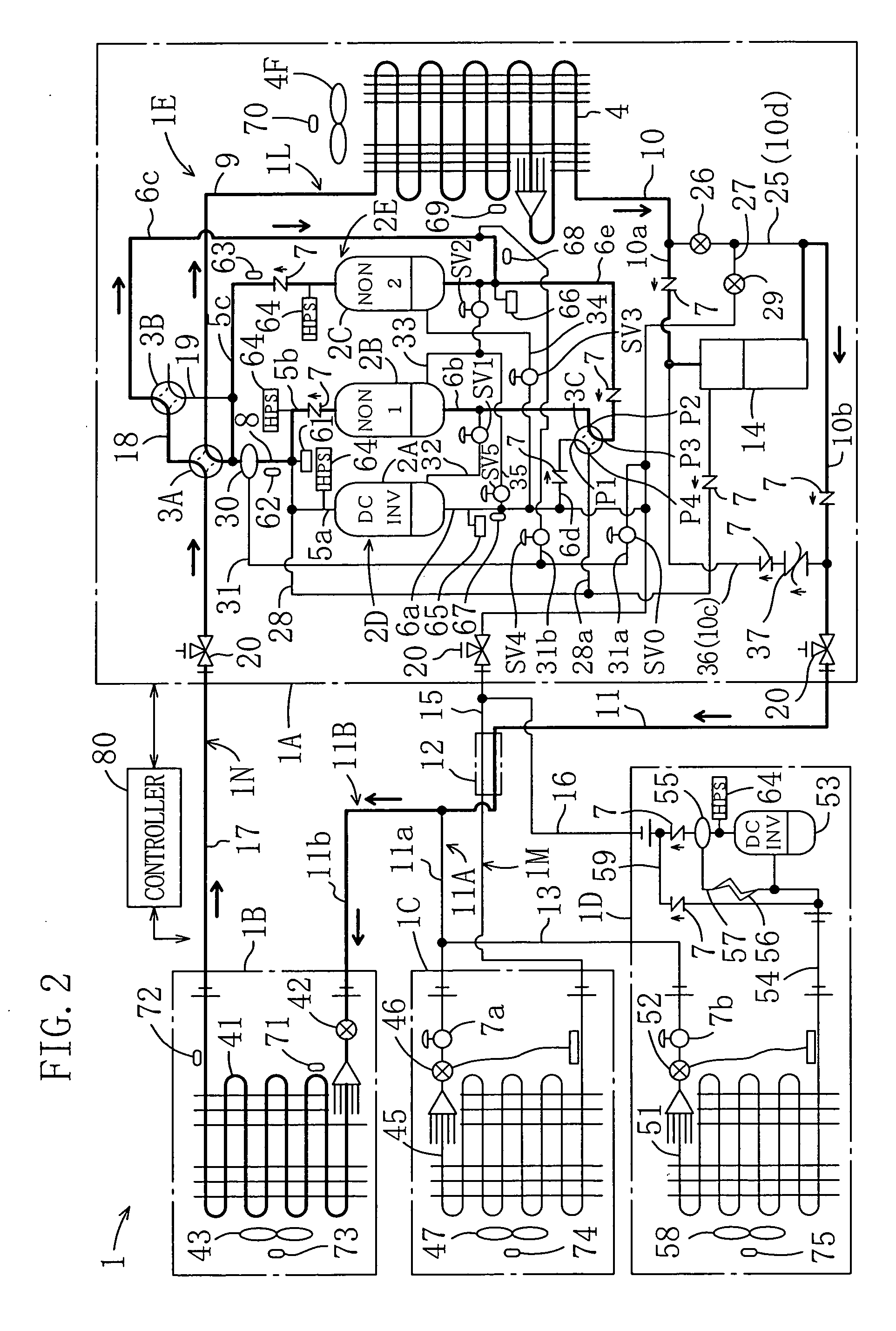
[0206] Hereafter, a second embodiment of the present invention will be described. With reference to FIG. 13 showing the second embodiment, there is provided a compression mechanism (2D, 2E) made up of two compressors (2A, 2B). In addition, in the second embodiment, a booster unit (1F) independent of the freeze storage unit (1D) is provided and the booster compressor (53) is housed within the booster unit (1F).

[0207] In the description which follows, differences between the first and second embodiments with regard to the outdoor unit (1A), the freeze storage unit (1D), and the booster unit (1F) will be explained (note that the same constructional parts as the first embodiment are not described here).

Outdoor Unit

[0208] The outdoor unit (1A) includes an inverter compressor (2A) as a first compressor and a noninverter compressor (2B) as a second compressor and further includes a first four-way switch valve (3A), a second four-way switch valve (3B), a third four-way switch valve (3C)...

Example

[0300] Hereafter, a third embodiment of the present invention is described. As shown in FIG. 21, the third embodiment is provided with a backflow prevention mechanism (liquid seal mechanism) that is a modification of the backflow prevention mechanism in the refrigerant circuit of the first embodiment.

[0301] More specifically, in the third embodiment, the gas vent pipe (28) of the first embodiment is not connected between the receiver's (14) upper part and the discharge pipe (5a) of the inverter compressor (2A). Instead, a liquid seal prevention pipe (38) is connected between a connecting point with the auxiliary liquid pipe (25) in the liquid injection pipe (27) and the electronic expansion valve (29). The liquid seal prevention pipe (38) is connected also to the high pressure gas pipe (8). The liquid seal prevention pipe (38) is provided with a check valve (7) which permits only one-way flow of refrigerant traveling from the liquid injection pipe (27) towards the high-pressure gas...


PUM


Abstract

In the case where a 100 percent heat recovery operation mode is performed without using an outdoor heat exchanger in a refrigeration apparatus which is provided with utilization-side heat exchangers of a plurality of piping systems and in which liquid-side communication lines are arranged into a single line, a backflow prevention mechanism (37) for preventing liquid refrigerant exiting an indoor heat exchanger (41) from flowing in a direction other than in the direction of cold storage and freeze storage heat exchangers (45, 51) is disposed for providing stable flow of refrigeration through the circuit even when the temperature of outside air is low, whereby the capability to provide refrigeration is prevented from degrading.

Description

TECHNICAL FIELD [0001] The present invention generally relates to a refrigeration apparatus and in particular to a refrigeration apparatus having a plurality of utilization-side heat exchangers as heat exchangers used for providing cold storing, freeze storing, and air conditioning. BACKGROUND ART [0002] Conventionally, refrigeration apparatuses which perform refrigeration cycles have been known in the prior art. Such a type of refrigeration apparatus has been used widely as an air conditioning apparatus for providing indoor space heating / cooling and as a cooler for a refrigerator or other like apparatus for keeping food, etc., cool. There is a refrigeration apparatus which is configured such that it provides both air conditioning and cold / freeze storing (see, for example, JP Patent Application Publication (Kokai) No. 2001-280749). [0003] Generally, in such a type of refrigeration apparatus, a plurality of utilization-side heat exchangers (heat exchangers for cold storage, freeze st...

Claims


Application Information

Patent Timeline
IPC IPC(8): F25B13/00F25B1/00F25B1/10F25B29/00F25B40/00F25B41/04
CPCF25B1/10F25B13/00F25B40/00F25B2313/007F25B2313/0231F25B2313/0233F25B2400/0751F25B2400/16F25B2400/22F25B2500/31F25B2600/021F25B2700/1931F25B2700/2106F25B2700/21171Y02B30/741Y02B30/70F25B5/02F25B1/00F25B29/00
Inventor TAKEGAMI, MASAAKITANIMOTO, KENJIUENO, TAKEOKAJIMOTO, AKIHIRO
Owner DAIKIN IND LTD
Why Eureka
Try Eureka