Position sensor, designed in particular for detecting a steering column torsion

a technology of position sensor and steering column, applied in the direction of engine lubrication, liquid/fluent solid measurement, electrical/magnetic means, etc., can solve the problems of loss of magnetic signal, loss of sensor structure, and poor prior art solution, and achieve the effect of better signal-to-noise ratio

Inactive Publication Date: 2006-06-15
MOVING MAGNET TECH
View PDF16 Cites 41 Cited by
  • Summary
  • Abstract
  • Description
  • Claims
  • Application Information

AI Technical Summary

Benefits of technology

[0009] The object of the present invention is to overcome these disadvantages by providing an improved position sensor with better signal-to-noise ratio.
[0010] Another object of the invention is to reduce the radial space requirement.

Problems solved by technology

This prior art solution is not satisfactory, because it leads to a loss of magnetic signal between the stator part and the part containing the Hall probe.
Furthermore, the magnetic field generated by the magnets leads to losses due to the sensor structure.
This structure also leads to magnetic leaks and to reduced efficiency, manifested by a poor “signal-to-noise” ratio.

Method used


Image

  • Position sensor, designed in particular for detecting a steering column torsion
  • Position sensor, designed in particular for detecting a steering column torsion
  • Position sensor, designed in particular for detecting a steering column torsion

Examples


Embodiment Construction

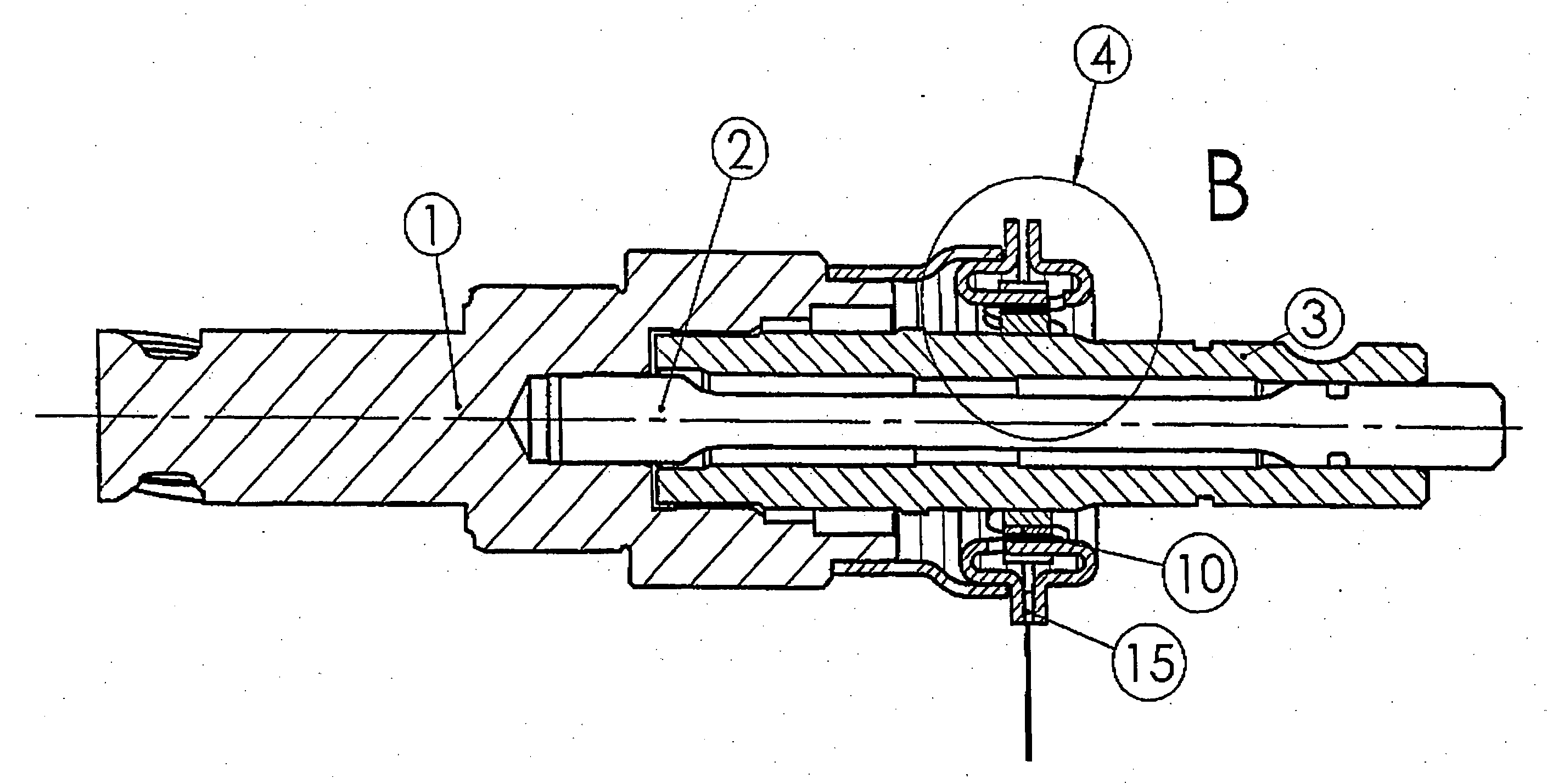
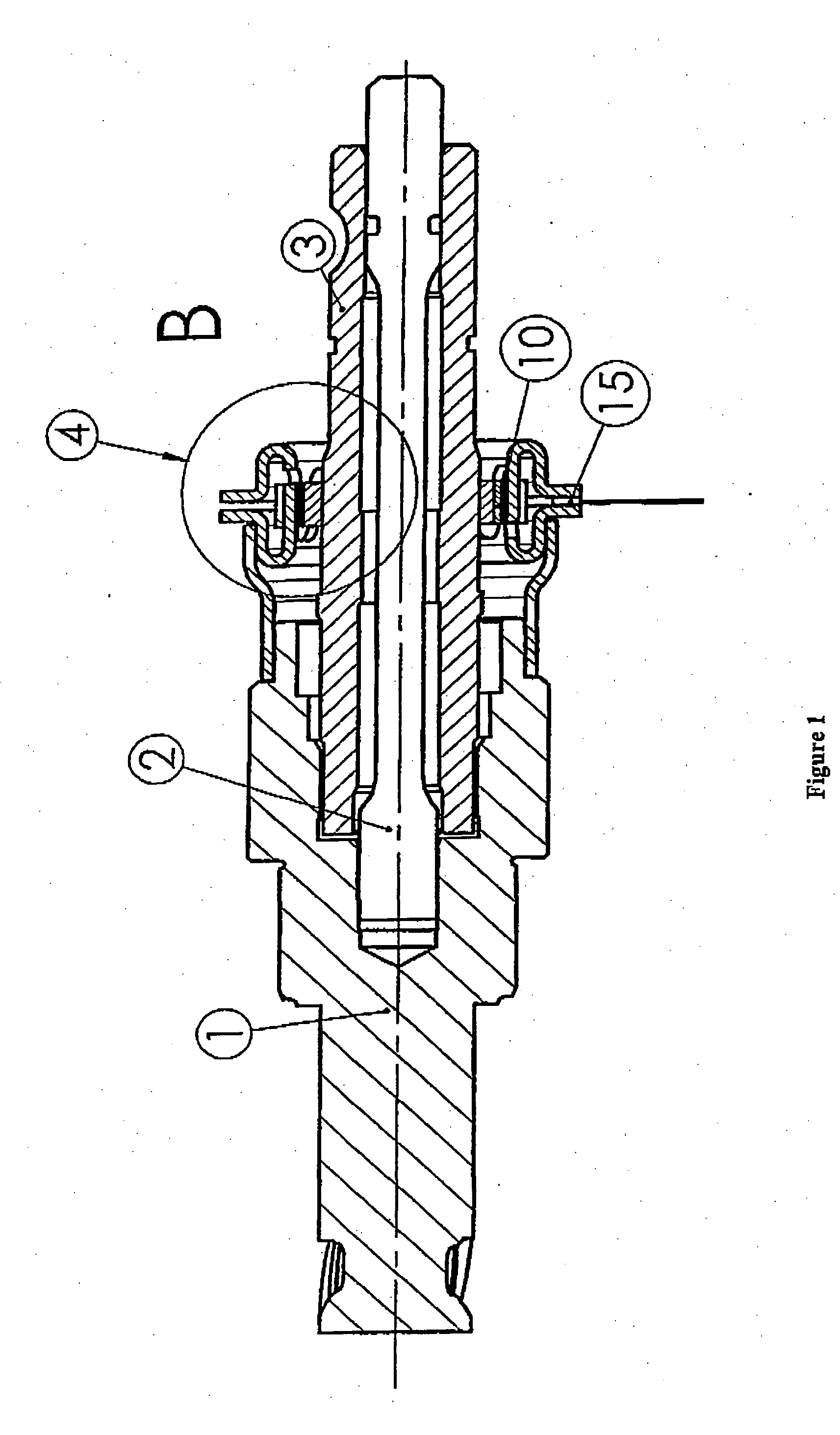
[0031] The object of the invention is to overcome these problems of low sensitivities and it relates to contactless position sensors intended for the measurement of angles similar to or smaller than 10° C., in applications such as steering-column torque sensors, for example (the signal then will be processed to provide steering assistance). The angular position sensor described hereinafter is intended for the measurement of a very small angular difference (a few degrees) between two shafts connected by a torsion bar. Such an application for torque measurement is described in FIG. 1. In the range of linear deformation of this torsion bar, this angular difference (α1-α2) will be proportional to the torque applied between the two shafts (1, 3) connected by an elastically deformable test member (2). The measurement of this angular difference by the sensor will allow an electrical signal proportional to the applied torque to be delivered at the output of the magnetosensitive element. In ...


PUM

PropertyMeasurementUnit
anglesaaaaaaaaaa
torsional working angleaaaaaaaaaa

Abstract

A position sensor, designed in particular for detecting a steering column torsion, including a first magnetic structure including a plurality of magnets and a second magnetic structure including two ferromagnetic rings having a plurality of teeth and defining an air gap. At least a magneto-sensitive element is placed in the air gap. The first and second magnetic structures are respectively integral with two parts in relative rotation. The two ferromagnetic rings are nested and have each a substantially tubular part forming axially oriented teeth connected by a flux-closing zone, the detecting air gap being delimited by the flux-closing zones.

Description

BACKGROUND OF THE INVENTION [0001] 1. Field of the Invention [0002] The present invention relates to the art of position sensors, and more particularly to position sensors intended to measure the torsion of a steering column, although such an application is not exclusive. [0003] 2. Description of the Related Art [0004] In the prior art there is known U.S. Pat. No. 4,984,474, which describes a prior art sensor provided with a stator part comprising a ferromagnetic piece forming radial teeth at two levels, disposed facing multi-pole magnets that are radially magnetized in alternating directions. [0005] An additional ferromagnetic piece is disposed facing the stator part, and forms an air gap in which there is placed a Hall probe. [0006] This prior art solution is not satisfactory, because it leads to a loss of magnetic signal between the stator part and the part containing the Hall probe. Furthermore, the magnetic field generated by the magnets leads to losses due to the sensor struct...

Claims


Application Information

Patent Timeline
Patent Type & Authority Applications(United States)
IPC IPC(8): G01F23/02B62D5/04G01B7/00G01B7/30G01L3/10
CPCG01L3/101G01L3/104
Inventor GANDEL, PIERREFRACHON, DIDIERANGLEVIEL, DIDIEROUDET, CLAUDEPRUDHAM, DANIEL
Owner MOVING MAGNET TECH
Why Eureka
Try Eureka