Methods and apparatus for drilling, completing and configuring U-tube boreholes

a technology for completing and drilling u-tubes, which is applied in the direction of borehole/well accessories, directional drilling, artificial islands, etc. it can solve the problems of affecting the environment, affecting the environment, and affecting the environment, and conventional above-ground pipelines are simply not acceptabl

Inactive Publication Date: 2006-06-15
HALLIBURTON ENERGY SERVICES INC
View PDF72 Cites 123 Cited by
  • Summary
  • Abstract
  • Description
  • Claims
  • Application Information

AI Technical Summary

Benefits of technology

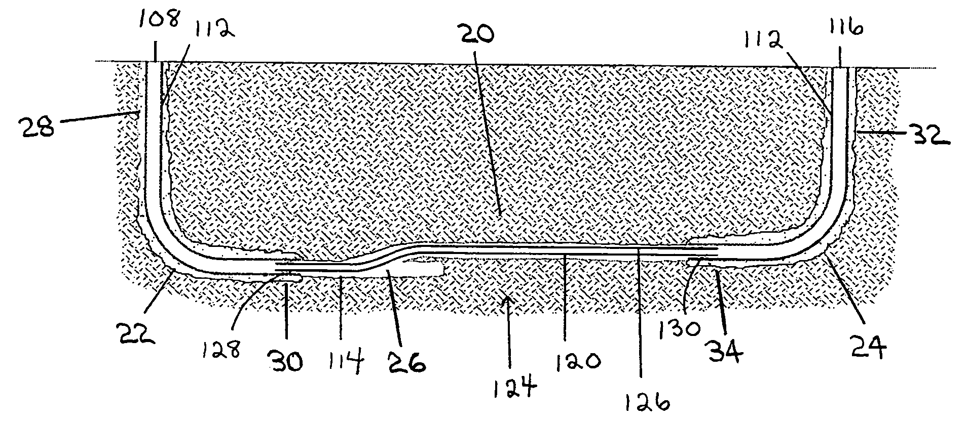
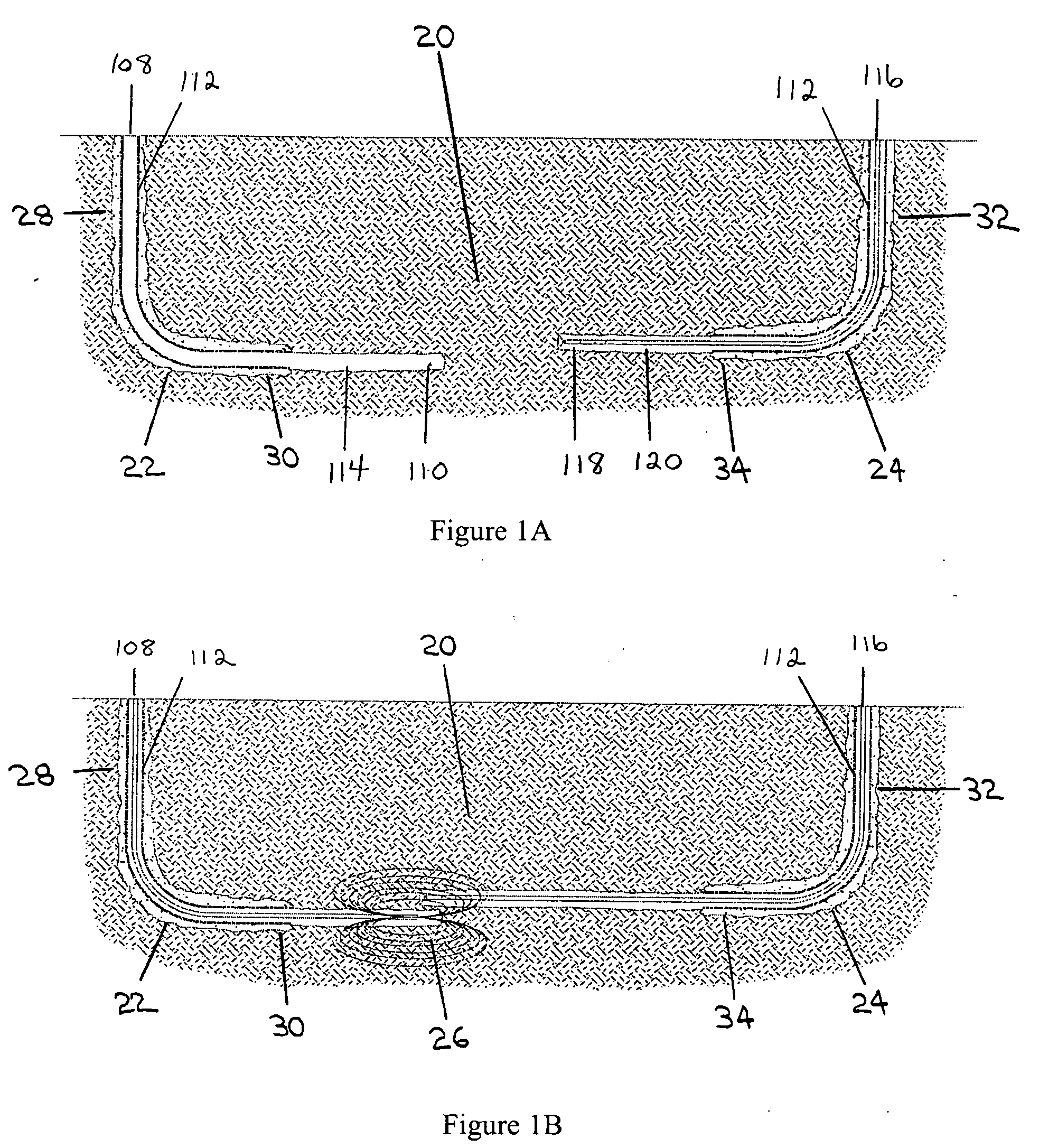
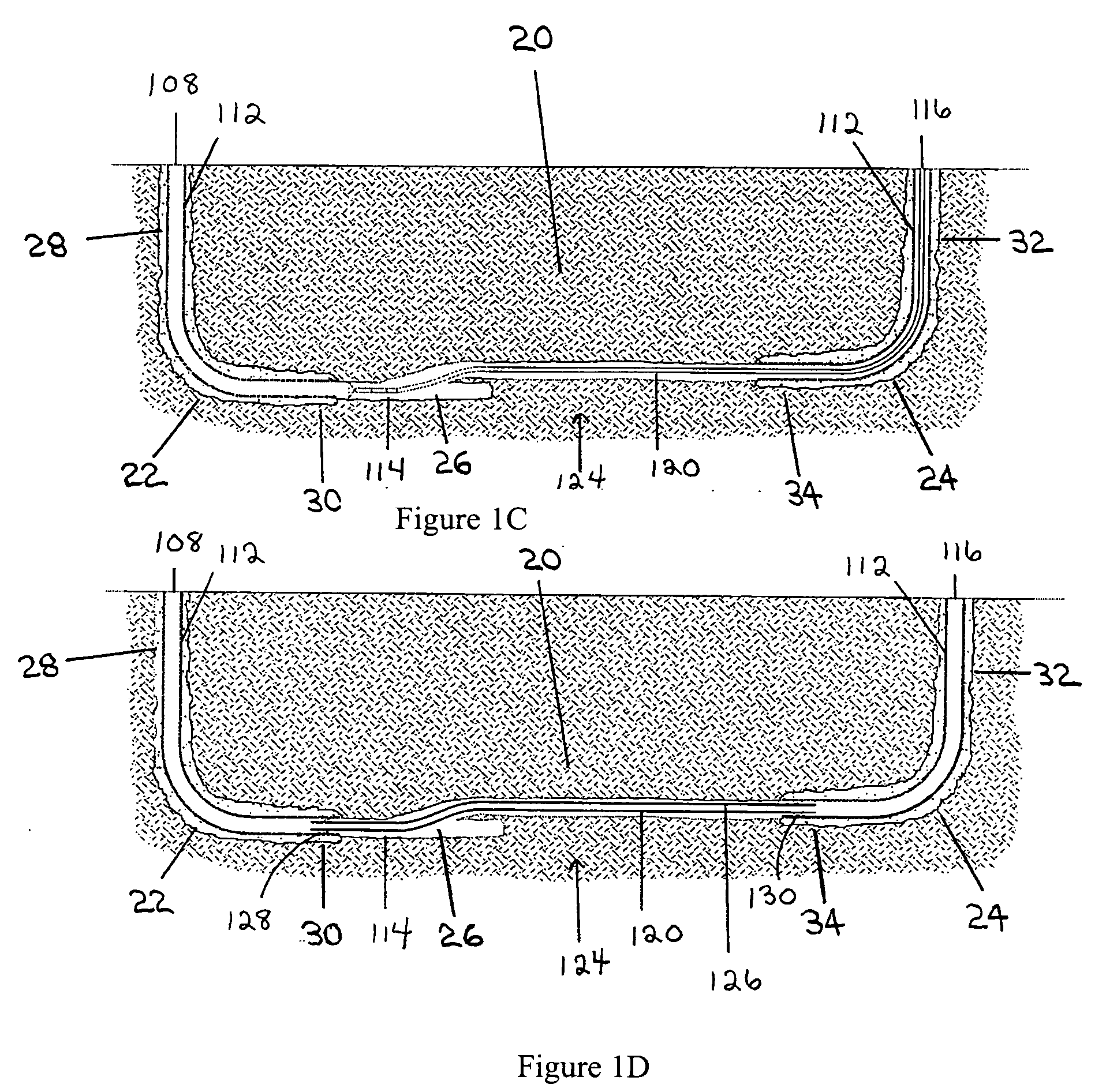
[0046] Fluid communication between the boreholes may be achieved through many different mechanisms. As a first example, fluid communication may be achieved by positioning the two boreholes in a relatively permeable formation so that gas and liquid can pass between the boreholes through the formation. As a second example, fluid communication can be achieved by creating fractures or holes in a relatively non-permeable formation between the boreholes using a perforation gun, a sidewall drilling apparatus, or similar device. As a third example, fluid communication can be achieved by washing away or dissolving a formation between the boreholes. For salt formations, water may be used to dissolve the formation. For carbonate formations such as limestone, acid solutions may be used to dissolve the formation. For loose sand or tar sand formations, water, steam, solvents or a combination thereof can be used to wash away or dissolve the formation. These techniques may be used in conjunction with slotted liners or screens located in one or both of the boreholes in order to provide borehole stability.
[0054] One or both of the opposed ends of the liner may be comprised of a conventional or known liner hanger for hanging or attaching the liner with one or both of the target or intersecting boreholes. Further, one or both of the opposed ends of the liner may be comprised of a conventional or known seal arrangement or sealing assembly in order to permit the end of the liner to be sealingly engaged with one or both of the target and intersecting boreholes and to prevent the entry of sand or other materials from the formation. Alternatively, one or both of the opposed ends of the liner may be extended to the surface. Thus, rather than extending only across the open hole interval, the liner may extend from one or both of the first and second surface locations and across the open hole interval.

Problems solved by technology

Other potential applications or benefits of the creation of a U-tube borehole include the creation of underground pipelines to carry fluids, which include liquids and / or gases, from one location to another where traversing the surface or the sea floor with an above ground or conventional pipeline presents a relatively high cost or a potentially unacceptable impact on the environment.
Further, such situations may exist where the pipeline is required to traverse a shoreline with high cliffs or sensitive coastal marine areas that can not be disturbed.
In addition, going across bodies of water such as lake beds, river basins or harbors may be detrimental to the environment in the event of breakage of an above ground or conventional pipeline.
In sensitive areas, conventional above ground pipelines would simply not be acceptable because of the environmental risk.
However, concerns regarding drag and the effects of gravity increase with the length of the borehole.
Further, conventional river crossing drilling rigs tend to have a limited reach.
In some instances, there is simply not enough lateral reach to drill down and then exit back up at the surface on the other side of the obstacle that is trying to be avoided.
Also, in the event that the borehole enters into a pressurized formation, exiting on the other side at the surface presents safety issues as no well control measures, such as a blow-out preventer (“BOP”) and cemented casing, are present at the exit point.
Further, in some areas of the world, such as offshore of the east coast of Canada, icebergs have rendered seabed pipelines impractical in some places since the iceberg can gouge long trenches in the sea floor as it floats by, thus tearing up the pipeline.
One disadvantage of passive magnetic ranging techniques is that they do require relatively accurate knowledge of the local magnitude and direction of the earth's magnetic field, since the magnetic field measurements which are taken represent a combination of the magnetism inherent in the target borehole and the local values of the earth's magnetic field.
A second disadvantage of passive magnetic ranging techniques is that they do not provide for control over the magnetic fields which give rise to the magnetic field measurements.
A disadvantage of active magnetic ranging techniques is that they do typically require access into the target borehole in order either to create the magnetic field or fields or to make the magnetic field measurements.

Method used


Image

  • Methods and apparatus for drilling, completing and configuring U-tube boreholes
  • Methods and apparatus for drilling, completing and configuring U-tube boreholes
  • Methods and apparatus for drilling, completing and configuring U-tube boreholes

Examples


example 1

Drilling of a U-Tube Borehole Using an MGT Ranging System

Project Goals and Objectives

[0350] The goals of this project were laid out as follows: [0351] 1. Apply current directional drilling technology to see if two horizontal wellbores could be intersected end to end. Success was defined as intersecting the two wellbores with the drill bit, and being able to enter the wellbore of the second well with the drilling assembly. [0352] 2. Run standard steel casing through the intersection to prove that the two wellbores could be linked with solid tubulars. Success was defined as being able to run regular 7″ casing through an 8¾″ intersection point without getting the casing stuck in the hole. [0353] 3. Join the two casing strings with a connection technique that eliminated sand production. It was agreed that the connection technique used on this first well would be as simple as possible. If this initial trial was successful, future work could be done on a more advanced connection techniq...

example 2

Drilling of a U-Tube Borehole Using RMRS

[0411] This Example details the drilling of a pipeline comprising a U-tube borehole using RMRS as a magnetic ranging system. After months of drilling difficulties, and over 5900 meters of drilled borehole, the borehole intersection was achieved and successful fluid communication between the first borehole and the second borehole was established. A full drift junction between the first borehole and the second borehole was established to facilitate casing the U-tube borehole. Liner was run into both boreholes and placed 3 meters apart, with the liner covering the borehole intersection. Cementing the liner was performed by pumping down the annulus of one of the boreholes, and up the annulus of the other of the boreholes. Conventional drilling bottom hole assemblies were used to clean out the liner's float equipment before the rigs positioned at the surface locations of the two boreholes were moved off location so the well head could be tied into...


PUM


Abstract

A borehole network including first and second end surface locations and at least one intermediate surface location interconnected by a subterranean path, and a method for connecting a subterranean path between a first borehole including a directional section and a second borehole including a directional section. A directional drilling component is drilled in at least one of the directional sections to obtain a required proximity between the first and second boreholes. An intersecting component is drilled, utilizing magnetic ranging techniques, from one directional section to provide a borehole intersection between the first and second boreholes, thereby connecting the subterranean path.

Description

FIELD OF INVENTION [0001] Methods and apparatus for drilling U-tube boreholes, for completing U-tube boreholes, and for configuring U-tube boreholes. BACKGROUND OF THE INVENTION [0002] There is a need in a variety of situations to drill, intersect and connect two boreholes together where the intersection and connection is done below ground. For instance, it may be desirable to achieve intersection between boreholes when drilling relief boreholes, drilling underground passages such as river crossings, or when linking a new borehole with a producing wellbore. A pair of such intersected and connecting boreholes may be referred to as a “U-tube borehole”. [0003] For example, Steam Assisted Gravity Drainage (“SAGD”) may be employed in two connected or intersecting boreholes, in which the steam is injected at one end of the U-tube borehole and production occurs at the other end of the U-tube borehole. More particularly, the injection of steam into one end of the U-tube borehole reduces the...

Claims


Application Information

Patent Timeline
Patent Type & Authority Applications(United States)
IPC IPC(8): E21B7/04
CPCE21B43/305
Inventor LEE, DEANHAY, RICHARD THOMASGIL, NESTOR HUMBERTOTEBBUTT, KYLERSCHNELL, RODNEY A.HESS, JOE E.GRILLS, TRACY LORNERYAN, BARRY GERARD
Owner HALLIBURTON ENERGY SERVICES INC
Why Eureka
Try Eureka