Liquid crystal display device having OCB mode and method of driving the same

a liquid crystal display and display mode technology, applied in static indicating devices, optics, instruments, etc., can solve the problems of low aperture ratio, needing further improvement, and light weight of personal computers, televisions and the like, etc., to reduce blurring effect, enhance brightness, and short time

Inactive Publication Date: 2006-06-15
SAMSUNG MOBILE DISPLAY CO LTD
View PDF6 Cites 32 Cited by
  • Summary
  • Abstract
  • Description
  • Claims
  • Application Information

AI Technical Summary

Benefits of technology

[0040] The present invention provides an OCB mode LCD with a decreased blurring effect and an enhanced brightness by using an external high voltage as a liquid crystal reset voltage and applyi

Problems solved by technology

In recent years, personal computers, televisions and the like have become lightweight and small in size, which requires lightweight and small-sized displays.
However, this method has a low aperture ratio and thus needs further improvement.
In addition, it is burdensome to form a separate color filter layer on an LCD substrate.
In addition, according to a conventional field sequential drive method, the actual display of the gray s

Method used


Image

  • Liquid crystal display device having OCB mode and method of driving the same
  • Liquid crystal display device having OCB mode and method of driving the same
  • Liquid crystal display device having OCB mode and method of driving the same

Examples


first embodiment

[0067]FIG. 7 is a timing diagram illustrating a method of driving an OCB mode LCD in accordance with the present invention.

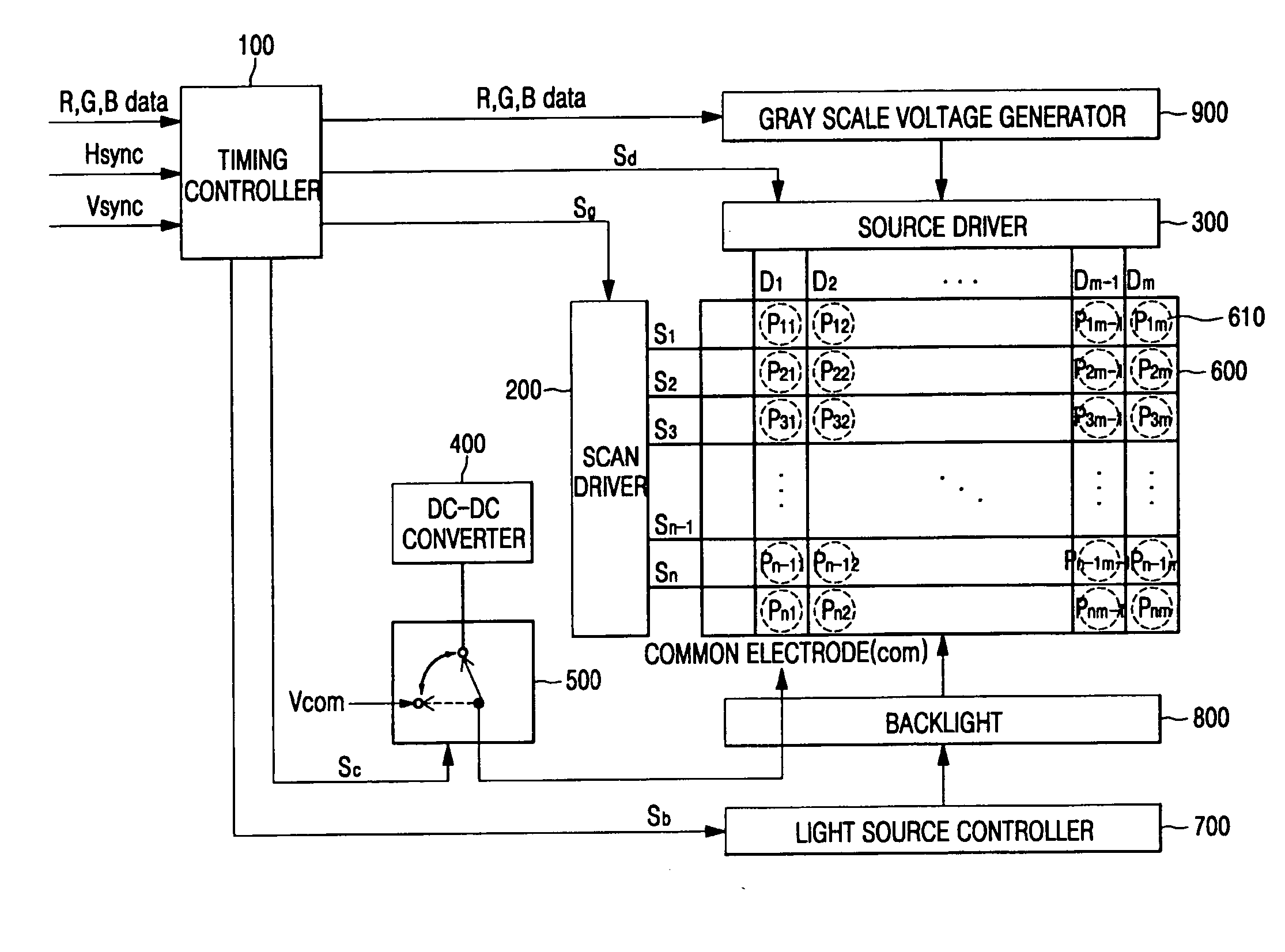
[0068] Referring to FIG. 7, an (n−1)th frame, an nth frame, and an (n+1)th frame among a plurality of frames are representatively shown. In this case, a term “frame” means that an image is represented on the LCD panel 600 by sequentially applying scan signals from a first scan line S1 to an nth scan line Sn from the scan driver 200, and sequentially applying data signals D1-Dm from a first data line D1 to an mth data line Dm from the source driver 300 in synchronization with the scan signals. In the case of a field sequential LCD, the backlight 800 sequentially emits light via a red LED, a green LED, and a blue LED. In addition, in the case of a color filter type LCD, the backlight 800 emits white light (e.g. WLED or CCFL), and has red, green, and blue color filters per unit pixel so that colors can be implemented via respective color filters.

[0069] Referring t...

second embodiment

[0076]FIG. 8 is a timing diagram illustrating a method of driving a field-sequential LCD having an OCB mode in accordance with the present invention.

[0077] Referring to FIG. 8 and the LCD shown in FIG. 6, in the field-sequential LCD, one frame is divided into red (R), green (G), and blue (B) fields. Each of the plurality of pixels 610 arranged in the LCD panel 600 in a matrix form sequentially displays three primary lights of R, G, and B colors output from the R, G, and B backlights in a time-division manner, thereby displaying a color image using an afterimage effect on vision.

[0078] When a first scan signal S1(R) is applied to a first scan line S1 from the scan driver 200 in the R field of the frame, pixels P11-P1m, which are connected to the first scan line S1 are selected. R data signals DR11-DR1m over data lines D1-Dm are provided from the source driver 300 to pixel electrodes as lower electrodes of liquid crystal capacitors CLC of the pixels P11-P1m, which are connected to th...

third embodiment

[0090]FIG. 9 is a timing diagram illustrating a method of driving an OCB mode LCD in accordance with the present invention.

[0091] Referring to FIG. 9 and the LCD shown in FIG. 6, in the method of driving the LCD according to the third embodiment of the present invention, when scan signals are sequentially applied to scan lines S1-Sn from the scan driver 200, a plurality of pixels P11-Pnm connected to the scan lines S1-Sn are sequentially selected, and data signals D11, D12, and D13 are provided from the source driver 300 to pixel electrodes as lower electrodes of liquid crystal capacitors CLC of the pixels P11-P1m, which are connected to the scan lines S1-Sn, respectively. In this case, a common electrode is an upper electrode of the liquid crystal capacitor CLC and is applied with a common voltage Vcom as a reference voltage while the scan lines S1-Sn are driven. In addition, while the scan lines S1-Sn are driven, the backlight 800 emits light sources, which are transmitted through...


PUM


Abstract

A liquid crystal display device (LCD) which applies a high voltage for carrying out a bend transition of an optically compensated birefringence (OCB) liquid crystal as a reset voltage to a common electrode of the OCB liquid crystal in the LCD having an OCB mode, and a method of driving the same are provided. In the OCB mode LCD, a voltage of a DC-DC converter is applied to a common electrode to reset the OCB liquid crystal at an initial stage of every frame or before applying data to each pixel. In addition, when one frame is divided into red, green and blue fields, and sequentially driven, a voltage of the DC-DC converter is applied to the common electrode to reset the OCB liquid crystal before each field begins. The DC-DC converter applies a voltage of 15V to 30V to the common electrode. An optical transmittance of the liquid crystal at the time of reset becomes zero (black state). Accordingly, a blurring effect can be removed while a reset time can be decreased, thereby increasing the brightness.

Description

CROSS-REFERENCE TO RELATED APPLICATIONS [0001] This application claims priority to and the benefit of Korean Patent Application No. 10-2004-0104487, filed Dec. 10, 2004, the contents of which are hereby incorporated herein by reference in their entirety. BACKGROUND OF THE INVENTION [0002] 1. Field of the Invention [0003] The present invention relates to a liquid crystal display device (LCD) and a method of driving the same, and more particularly, to an optically compensated bend or birefringence (OCB) mode LCD and a method of driving the same, which applies a high voltage for carrying out a bend transition of an OCB liquid crystal as a reset voltage to a common electrode of the OCB liquid crystal. [0004] 2. Description of the Related Art [0005] In recent years, personal computers, televisions and the like have become lightweight and small in size, which requires lightweight and small-sized displays. Consequently, flat panel displays such as liquid crystal display devices (LCD) have ...

Claims


Application Information

Patent Timeline
IPC IPC(8): G09G1/08
CPCG09G3/3413G09G3/3655G09G2300/0491G09G2310/0235G09G2310/061G09G2320/0261G02F1/133
Inventor CHOI, KYUNG-HO
Owner SAMSUNG MOBILE DISPLAY CO LTD
Why Eureka
Try Eureka