Optical network, optical edge router, program thereof, cut through method, and edge router

Inactive Publication Date: 2006-06-15
NIPPON TELEGRAPH & TELEPHONE CORP
View PDF10 Cites 19 Cited by
  • Summary
  • Abstract
  • Description
  • Claims
  • Application Information

AI Technical Summary

Benefits of technology

[0037] An object of the present invention is to provide an optical network, etc. fo

Problems solved by technology

However, the addresses existing in the same space as the external IP networks are used for controlling the optical paths; therefore, there is a problem in containing a plurality of external IP networks in an optical network.
Therefore, in contrast to the peer model, it is characterized in that, providing multi-layer cooperative functions is difficult, but that it is easy to contain a plurality of networks.
If the neighborhood relationships of the routing operation change, instability increases in the external IP networks because the external IP networks acknowledge that the topologies are being changed in the network.
In general, the IP interfaces are expensive because complicated IP processes, i.e., retrieving the IP addresses, are conducted.
Also, such a complication is a bottle neck for increasing interface speeds.
On the other hand, in these core networks, the optical paths are realized by wavelength or logical connection of the layer 2; therefore, number of the connections which can be established by e

Method used


Image

  • Optical network, optical edge router, program thereof, cut through method, and edge router
  • Optical network, optical edge router, program thereof, cut through method, and edge router
  • Optical network, optical edge router, program thereof, cut through method, and edge router

Examples


Example

[0094] A first embodiment for implementing the present invention will be explained in detail with reference to drawings.

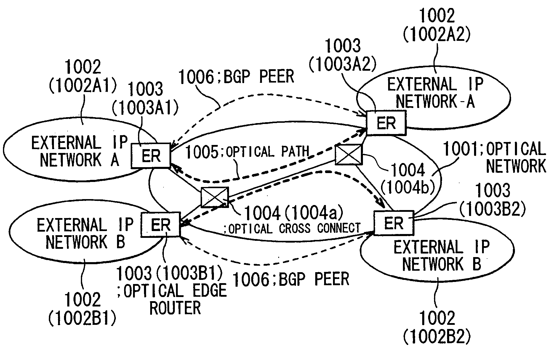
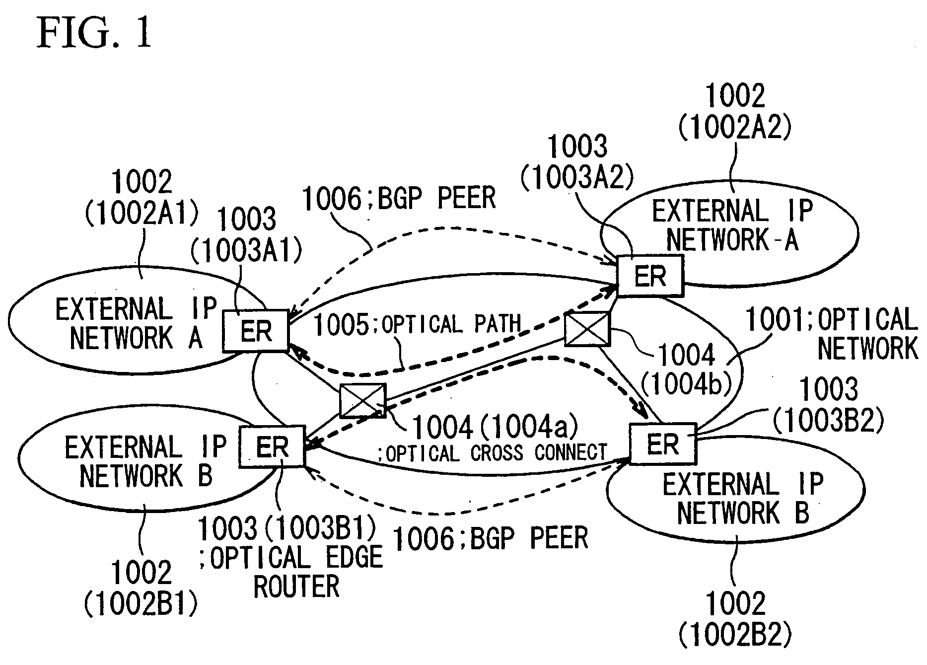
[0095]FIG. 1 is a view showing a general structure of an optical network including external IP networks.

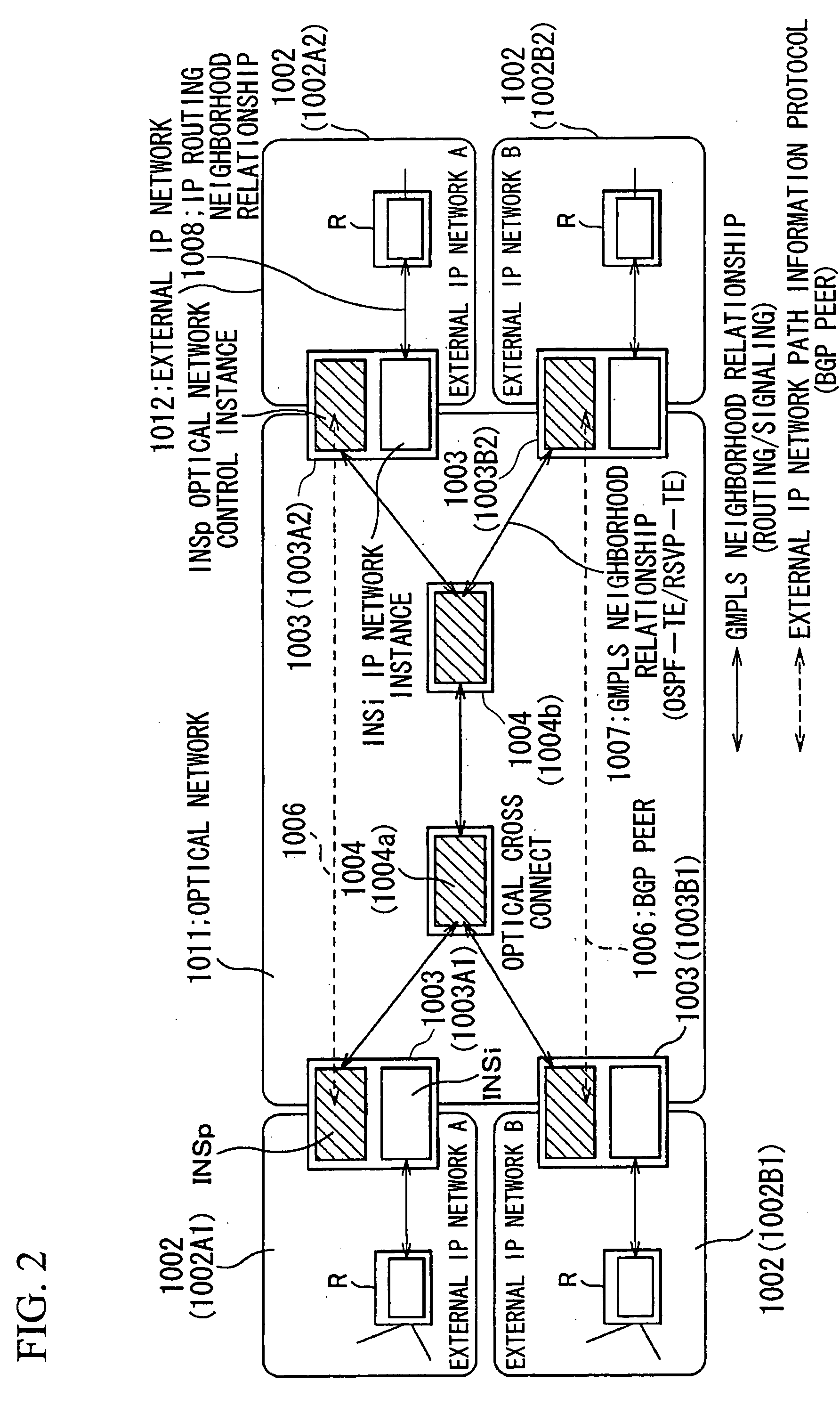
[0096] As shown in FIG. 1, an optical network 1001 includes two sets of external IP networks 1002A and 1002B1, consisting of, i.e., totally 4 (four) sites: 1002A1, 1002A2, 1002B1, and 1002B2. The external IP networks 1002A2 and 1002B2 are contained in the optical network 1001 via edge routers 1003 so that an optical path 1005 is established among the optical edge routers 1003 through optical cross connects (optical cross connect device) 1004 (1004a, 1004b . . . ). Also, BGP peers 1006 are established among the optical edge routers 1003 for exchanging route information of the external IP networks. GMPLS is used for a protocol for controlling the optical paths in the optical network.

[0097] The GMPLS, used in the present embodiment, is a technique for routing sig...

Example

[0134] A second embodiment of the present invention will be explained with reference to FIGS. 7 to 10. FIG. 7 is a schematic diagram for explaining an optical network. FIG. 8 is a view for explaining details of optical cutting-through processes. FIG. 9 is a view explaining an MPLS label table. FIG. 10 is a view for explaining a structure of the edge routers for realizing the optical cut-through.

[0135] As shown in FIG. 7, the present embodiment is an edge router comprising: an optical network 2001 as a core network; a plurality of external IP networks 2002, the networks 2001 and 2002 being connected at border points. As shown in FIG. 8, the edge router further comprises: IP / MPLS interface 2017 for processing incoming IP packets transmitted from the external IP networks 2002 to the optical network 2001; and an MPLS interface 2020 for processing outgoing IP packets transmitted from the optical network 2001 to the external IP networks 2002.

[0136] The present embodiment is characterize...

Example

Embodiment 3

[0154]FIG. 16 is a view for explaining a structure of the data transmission network in a third embodiment of the present invention.

[0155] A plurality of line exchangers 3200 form a line exchange network in which at least communication lines 3300 are connected. A plurality of packet exchangers 31000 are connected to the line exchangers in this line exchange network via the communication lines 3300; thus, a packet exchange network is formed.

[0156] The line exchangers 3200 are formed by line switches and sections for controlling line paths.

[0157] The line switches are connected line switches in at least one other line exchanger via a plurality of communication lines.

[0158] The section for controlling line paths controls the line switches and combines two communication lines. The communication line is, i.e., an optical line, an SDH / SONET line, an ATM line, an MPLS-LSP line, or an FR line. The section for controlling line paths is connected to at least the section for co...


PUM


Abstract

An optical network has: sections for establishing optical paths; a plurality of optical edge routers for connecting external IP networks to the optical network (1001); and a plurality of optical cross connects, for connecting the optical edge routers by the optical paths, having switching sections with respect to an optical pulse unit. In the optical network, each of the optical edge routers has both of: (1) an optical network control instance (INSp) for maintaining topology information in the optical network and switching/signaling the optical paths; and (2) an IP network instance (INSi) for maintaining a routing table in each of the external IP networks and activating routing protocols between the external IP networks and the IP network instance. By doing this, it is possible to realize a multi-layer cooperative function and provide highly safe optical networks, etc.

Description

TECHNICAL FIELD [0001] The present invention relates to an optical network formed in a plurality of routers and optical cross connects, an optical edge router, and a program therefor. [0002] Also, the present invention relates to a communication method in a core network having connections realized by a light or a layer 2 path. In particular, the present invention relates to a cutting-through method. [0003] Also, the present invention relates to an information transmission network system, a packet exchanger and a packet / line exchanger for transmitting data. In particular, the present invention relates to a technology for establishing transmission lines for transmitting data for realizing the transmission of the data. BACKGROUND ART [0004] Conventionally, techniques (optical IP techniques) for establishing paths, i.e., TDM (Time Division Multiplexing) channels and wavelengths, by signaling protocols which can be activated in an IP (Internet Protocol) layer have been developed. For the...

Claims


Application Information

Patent Timeline
IPC IPC(8): H04L12/56H04L12/28H04L45/52H04L45/50H04L45/74H04Q11/00
CPCH04L45/04H04L45/50H04L45/52H04L45/54H04Q2011/0088H04Q11/0062H04Q11/0066H04Q11/0071H04L45/62
Inventor KOJIMA, HISASHIKURIMOTO, TAKSHIINOUE, ICHIROTAKEDA, TOMONORIMIYAMURA, TAKASHIKABASHIMA, KAISUKEMATSUURA, NOBUAKIAOKI, MICHIHIROURUSHIDANI, SHIGEO
Owner NIPPON TELEGRAPH & TELEPHONE CORP
Why Eureka
Try Eureka