Eureka AIR delivers breakthrough ideas for toughest innovation challenges, trusted by R&D personnel around the world.

Optical filtering device and method

a filter device and optical filter technology, applied in the field of optical filter devices, can solve the problems of laser unidirectional operation, laser center distribution, laser cavity design, etc., and achieve the effect of suppressing transmission peaks

Inactive Publication Date: 2006-06-15
LAMBDA CROSSING
View PDF6 Cites 13 Cited by
  • Summary
  • Abstract
  • Description
  • Claims
  • Application Information

AI Technical Summary

Benefits of technology

[0009] There is a need in the art for, and it would be useful to have, a novel tunable laser device enabling effectively suppressing transmission peaks at wavelengths other than a selected wavelength.
[0012] According to one embodiment of the invention, the optical coupler structure comprises a coupling region between an input / output waveguide connected to the input / output of the gain section and first and second waveguides. The optical coupler thus enables splitting of input light propagating in the input / output waveguide from the gain section into first and second light portions of substantially equal power and direct these light portions to propagate along two spatially separated paths in the first and second waveguides, respectively, and enables combining of light coming from these two paths to propagate through the input / output waveguide to the gain section.

Problems solved by technology

However, statistical variation associated with the manufacture of an individual DBR and DFB laser results in distribution of the center of the fixed wavelength.
Such a laser is unidirectional in its operation.
The use of ring resonators in a laser thus presents a problem in designing the laser cavity.

Method used


Image

  • Optical filtering device and method
  • Optical filtering device and method
  • Optical filtering device and method

Examples


Embodiment Construction

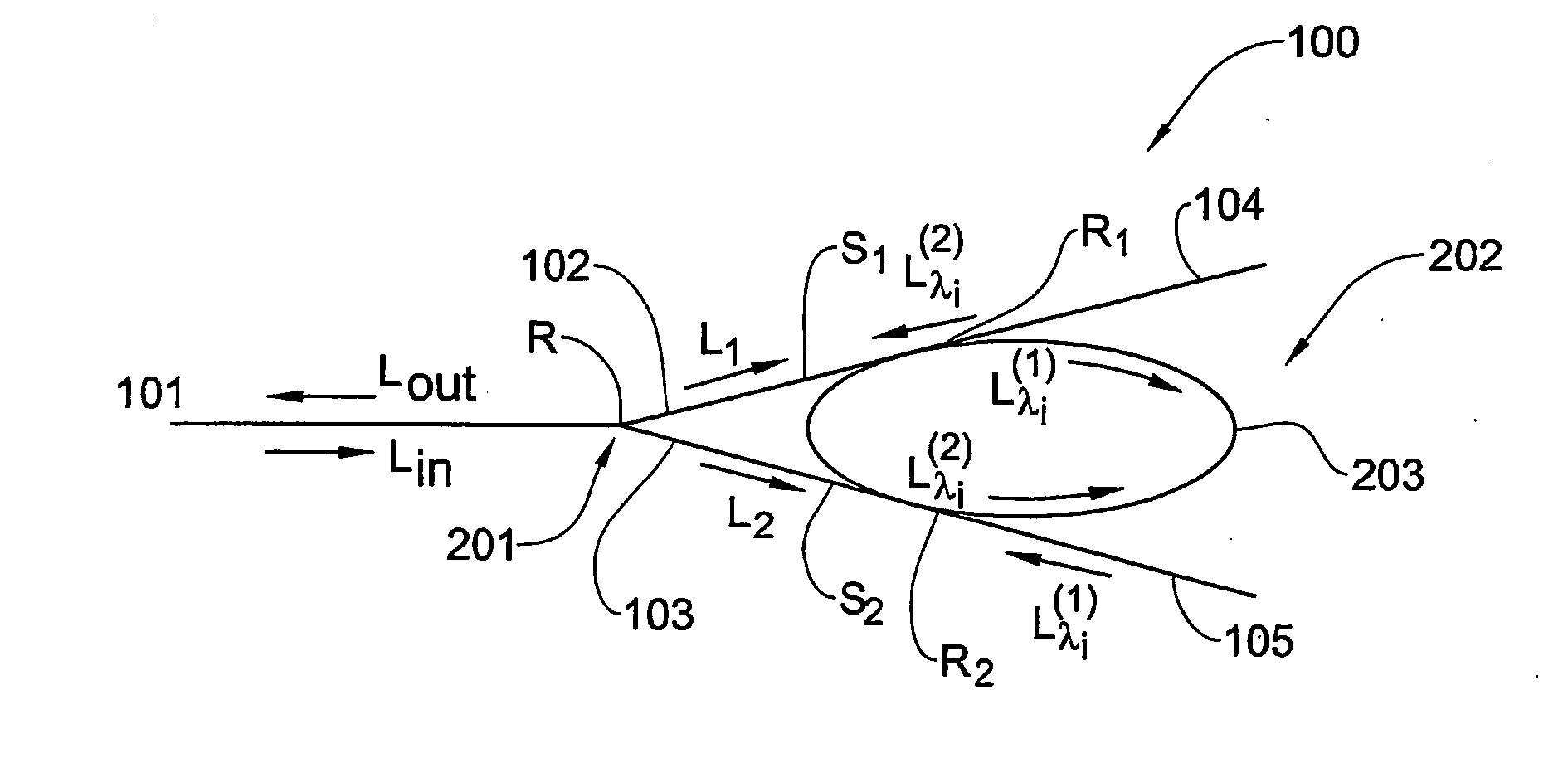
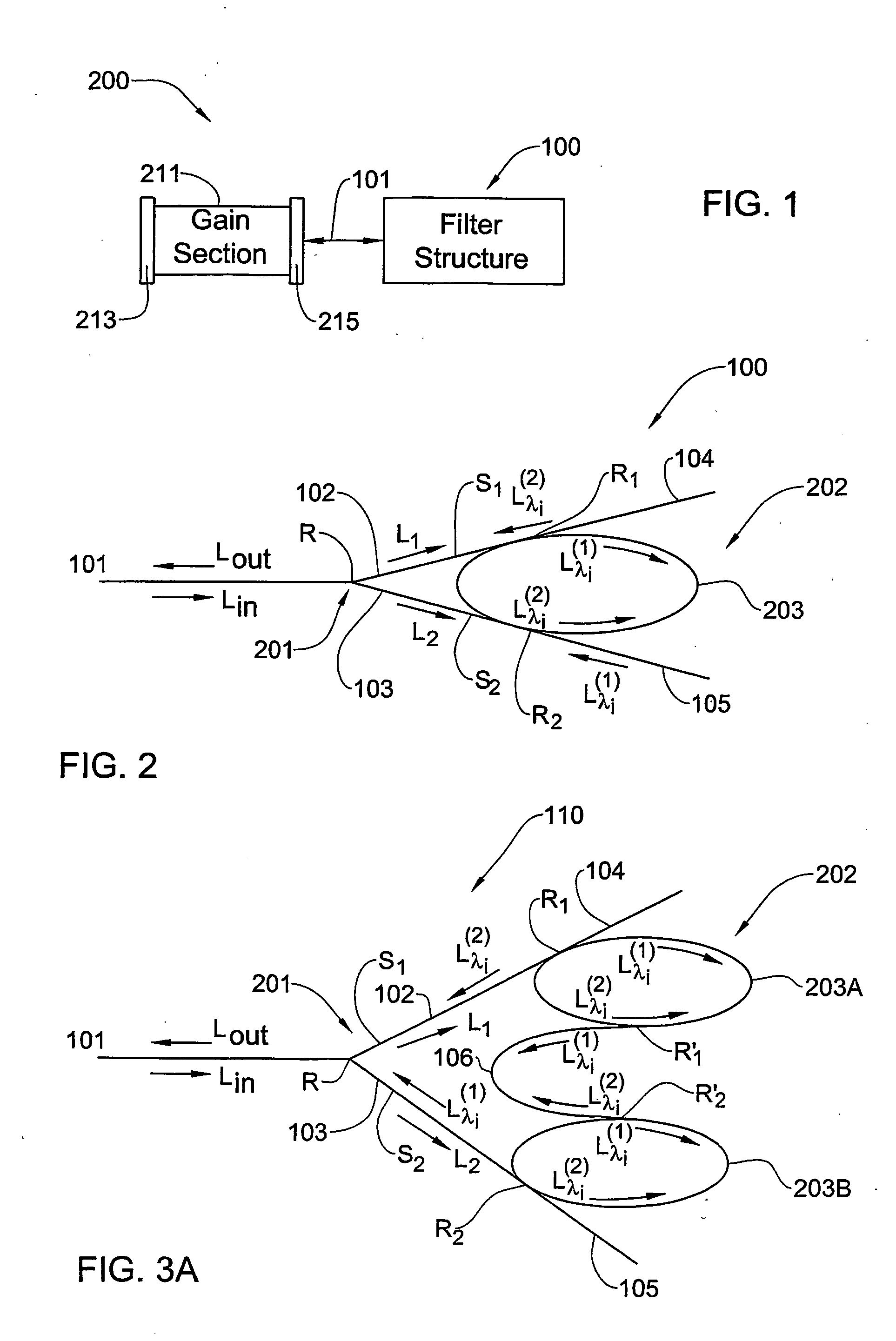
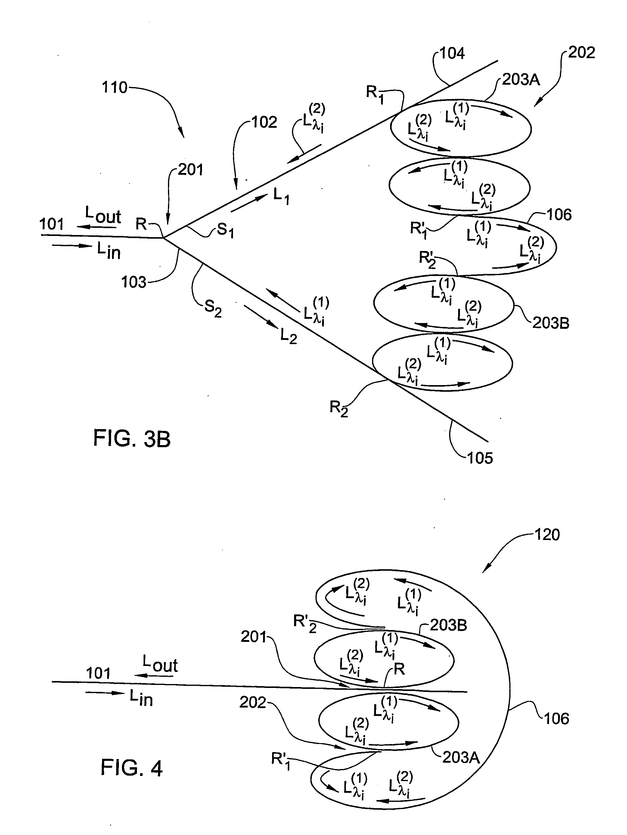
[0033] The principles and operation of the bi-directional wavelength selective filter structure according to the present invention and a laser device utilizing the same may be better understood with reference to the drawings and the accompanying description, it being understood that these drawings and examples in the description are given for illustrative purposes only and are not meant to be limiting. The same reference numerals will be utilized for identifying those components, which are common in all the examples shown in the drawings throughout the present description of the invention. It should be noted that the blocks in the drawings are intended as functional entities only, such that the functional relationships between the entities are shown, rather than any physical connections and / or physical relationships.

[0034] Referring to FIG. 1, there is illustrated, by way of a block diagram,. a tunable external cavity laser device 200 according to the invention. The laser device 20...


PUM


Abstract

A wavelength selective filter device is presented suitable for use as a part of a laser cavity for processing light output of a gain section of the laser cavity. The filter structure comprises a resonator structure including at least one closed-loop resonator; and defines an optical coupler structure for coupling light from an input / output of the gain section to propagate through said resonator structure, and a light reflector structure for reflecting light filtered by said resonator structure to propagate through said resonator structure to said input / output of the gain section. The filter structure is configured so as to define two optical paths of substantially the same lengths for light propagation in the resonator structure from and to the coupler structure.

Description

FIELD OF THE INVENTION [0001] This invention is generally in the field of optical devices, and relates to a tunable filter structure based on waveguides and micro-resonators, and a laser device utilizing the same. BACKGROUND OF THE INVENTION [0002] The demand for increased bandwidth in fiberoptic telecommunications has driven the development of semiconductor transmitter lasers usable for propagation multiple data streams concurrently in a single optical fiber. In addition to telecommunication applications, semiconductor lasers are now commonly used within audio, visual and personal computer systems where they are employed in the read and, where applicable, write heads of CD, CDROM and DVD units. [0003] Usually, semiconductor lasers operate with a wavelength spectrum consisting of a group of several closely spaced wavelengths. However, many applications require the single wavelength operation, narrow linewidth characteristics. This can be achieved by using a wavelength selective filt...

Claims


Application Information

Patent Timeline
Patent Type & Authority Applications(United States)
IPC IPC(8): G02B6/26H01S3/083H01S5/026H01S5/10H01S5/14
CPCH01S5/026H01S5/1032H01S5/141H01S5/142H01S5/146
Inventor MARGALIT, MOTIYASIN, MICHAELORENSTEIN, MEIR
Owner LAMBDA CROSSING
Why Eureka
Eureka Blog
Learn More