
Separator for fuel cell and fuel cell using it

a fuel cell and separator technology, applied in the field of separators, can solve the problems of degrading cell performance, corroding immediately, iron ion elution, etc., and achieve the effects of increasing the pressure of the reaction gas supplied, good sealing characteristic, and sufficient sealing characteristi

Inactive Publication Date: 2006-06-15
HITACHI LTD
View PDF6 Cites 13 Cited by
  • Summary
  • Abstract
  • Description
  • Claims
  • Application Information

AI Technical Summary

Benefits of technology

[0014] The separator according to the present invention can exhibit an excellent sealing characteristic to a gas and water, because the resinous frame member and the sealing material are formed integrally with each other. In addition, the sealing material itself functions as a structure forming the gas channel and hence, the channel for introducing the gas from the manifold to the electrode can be made without recourse to a machining or an injection molding.
[0017] It is also desirable that the sealing rubber integrated with the resinous frame member is formed on both of the surface and the back of the resinous frame member. The sealing frame is disposed between the metallic pressed plate and the electrolyte membrane, and the sealing rubber is a structure which is in close contact with the metallic pressed plate. However, the sealing between the electrolyte membrane and the sealing frame is a surface sealing, and there is a possibility that a sufficient sealing characteristic is not necessarily obtained, due to the utilization of the elasticity of the electrolyte membrane. It is possible to accommodate an increase in pressure of the reaction gas supplied to the cell by forming the sealing material even on the side of the sealing frame adjacent the electrolyte membrane.
[0018] Further, it is desirable that the sealing material is formed of at least two types of elastomers different in hardness. In the sealing frame, the sealing material integrated with the resinous frame member functions as a structure which seals the reaction gas and cooling water and forms the gas channel. If the structure forming the gas channel is deformed by a clamping pressure required by the cell, the gas flowing through the channel is disturbed to causes an influence to the performance of the cell. If the portion functioning as the sealing material is not crashed moderately by the clamping pressure for the cell, a good sealing characteristic is not obtained. The sealability can be enhanced by ensuring that the sealing rubber is different in rubber hardness within the same sealing frame.

Problems solved by technology

If, for example, a carbon steel having a low corrosion resistance is used, it is immediately corroded, whereby iron ion is eluted.
As a result, the performance of the cell is degraded, and the deterioration of the cell is advanced.

Method used


Image

  • Separator for fuel cell and fuel cell using it
  • Separator for fuel cell and fuel cell using it
  • Separator for fuel cell and fuel cell using it

Examples


embodiment 1

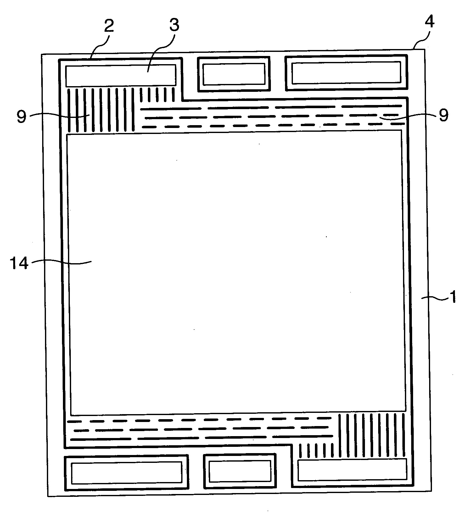
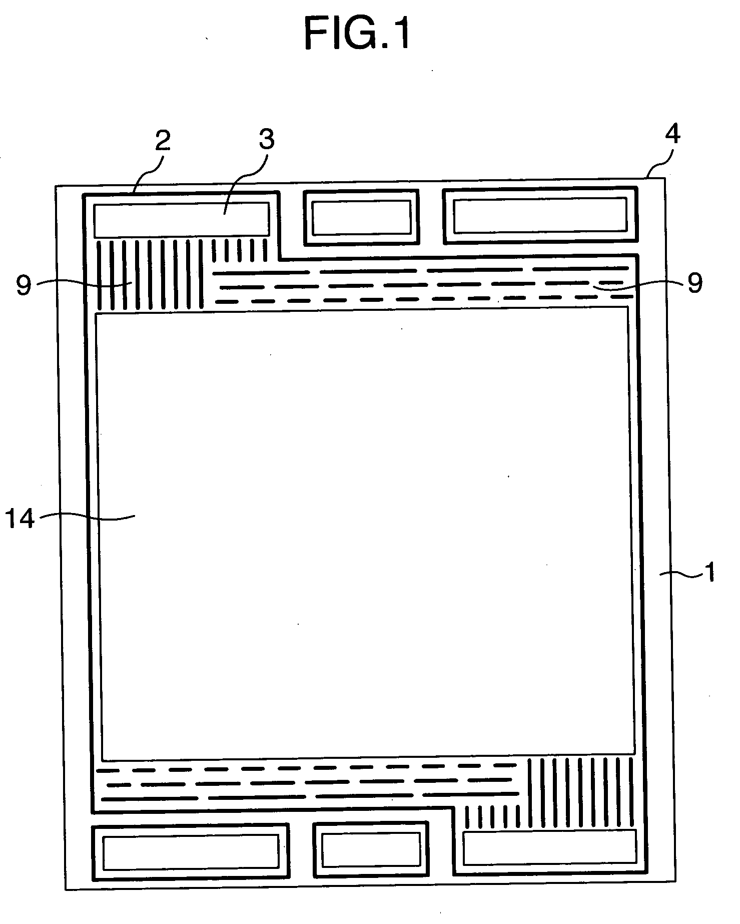
[0029] A varnish of an ethylene propylene diene monomer rubber (EPDM) was formed by a screen printing process on a resinous frame member 1 formed of a plate of polyphenylene sulfide (PPS) which was formed by a punching into a predetermined contour with a manifold 3 and a bore made for an electrode surface and which had a thickness of 0.2 mm. Then, the varnish was baked at a temperature of 150° C. in an air atmosphere to form a sealing material 2. The sealing material 2 forms a sidewall portion of a gas channel 9 for introducing a gas required for an electrochemical reaction from the manifold 3 to an electrode surface of a fuel cell. A sealing frame 4 is formed by the resinous frame member 1 and the sealing material 2. FIG. 1 is a plan view of the sealing frame. Reference numeral 14 in Figures denotes a perforation opened in the electrode surface. The sealing material has a height of 0.25 mm as formed, and EPDM has a rubber hardness of 60 degree. The rubber hardness is a value based ...

embodiment 2

[0031] A separator in the embodiment 2 was produced in the same manner as in the embodiment 1, except that titanium was clad on opposite surfaces of a stainless steel (SUS316) to form a metallic pressed plate having a three-layer structure and a thickness of 0.2 mm.

embodiment 3

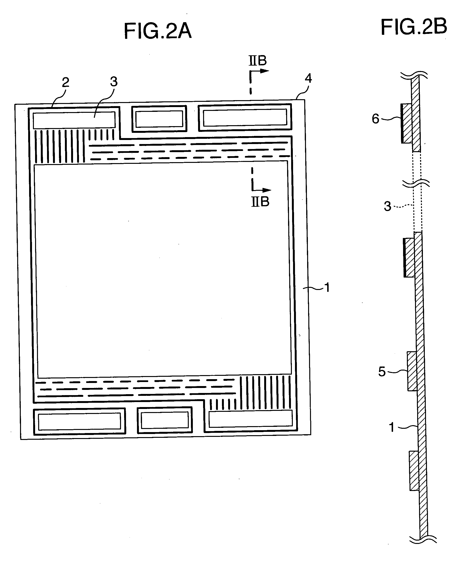
[0032] A separator in the embodiment 3 was produced using the same metallic pressed plate as in the embodiment 2 and using a sealing frame-producing process different from that in the embodiment 1. The sealing frame-producing process is as follows: An EPDM varnish was formed by a screen printing process on a PPS plate formed at a thickness of 0.2 mm into a predetermined contour by a punching, and then baked at 150° C. in an air atmosphere. Thereafter, a second printing was conducted with the screen plate replaced by new one, and the baking at 150° C. in an air atmosphere was conducted again. A plan view of a sealing frame produced is shown in FIG. 2A, and a sectional view taken along a line IIB-IIB in FIG. 2A is shown in FIG. 2B. A sealing material 2 has a height of 0.23 mm at a portion 5 formed by the first printing, and a height of 0.26 mm at a portion 6 formed by the second printing, because the portion 6 was piled on the portion formed by the first printing. The sealing frame ha...


PUM

PropertyMeasurementUnit
thicknessaaaaaaaaaa
thicknessaaaaaaaaaa
temperatureaaaaaaaaaa

Abstract

The present invention provides a separator for a fuel cell constructed using a metallic pressed plate, in which a gas channel from a manifold to an electrode surface is formed simply, and a good sealing characteristic is realized. The separator is comprised of a metallic pressed plate, a resinous frame member, and a sealing frame having a sealing material integrated therewith, and a channel for introducing a gas from the manifold to an electrode surface is formed by a metallic surface, the sealing material and a resinous surface. An elastomer such as a rubber is used for the sealing material. Thus, the gas channel from the manifold to the electrode surface can be formed simply, and an excellent sealing characteristic to the gas and water is obtained.

Description

BACKGROUND OF THE INVENTION [0001] 1. Field of the Invention [0002] The present invention relates to a fuel cell for taking out an electric energy directly from a fuel and an oxidizing agent by utilizing an electrochemical reaction, and particularly, to a separator. [0003] 2. Description of Related Art [0004] A solid polymer fuel cell using a solid polymer ion-exchange membrane, e.g., a proton-conductive polymer film for an electrolyte is a power-generating system which is currently at a phase of the research and development, but one of subjects aimed at the practical use is that the material cost is higher. One of costly materials is a separator, also known as a bipolar plate. The separator is a designation for an electron-conductive plate provided with a gas channel and adapted to isolate two types of reaction gases so as to prevent them from being mixed with each other. When the fuel cell is generating a power, the internal environment is corrosive and hence, it is desired that t...

Claims


Application Information

Patent Timeline
Patent Type & Authority Applications(United States)
IPC IPC(8): H01M8/02H01M2/08
CPCH01M8/0206H01M8/021H01M8/0221H01M8/0223H01M8/0247H01M8/0273H01M8/0284Y02E60/50
Inventor YAMAGA, KENJIYAMAUCHI, HIROSHI
Owner HITACHI LTD
Learn More