Method and system for providing a highly textured magnetoresistance element and magnetic memory

a magnetoresistance element and magnetic memory technology, applied in the field of magnetic memory systems, can solve the problems of increasing power consumption, adversely affecting the utility and reliability of such conventional magnetic elements, and affecting the utility and reliability of such conventional magnetic elements, and achieve the effect of reducing the write curren

Inactive Publication Date: 2006-06-15
GRANDIS
View PDF24 Cites 60 Cited by
  • Summary
  • Abstract
  • Description
  • Claims
  • Application Information

AI Technical Summary

Benefits of technology

[0014] According to the method and system disclosed herein, the present invention provides a magnetic element having a higher signal and that can be written using spin transfer at a lower write current.

Problems solved by technology

Use of a high critical current for switching the magnetization 19 / 19′ adversely affects the utility and reliability of such conventional magnetic elements 10 / 10′ in a magnetic memory.
The use of a high write current is associated with increased power consumption, which is undesirable.
In addition, the conventional magnetic element 10′, which has a higher resistance and thus a higher signal, may be less reliable because the conventional barrier layer 16′ may be subject to dielectric breakdown at higher write currents.
Thus, even though a higher signal read may be achieved, the conventional magnetic elements 10 / 10′ may be unsuitable for use in higher density conventional MRAMs using spin transfer to write to the conventional magnetic elements 10 / 10′.

Method used


Image

  • Method and system for providing a highly textured magnetoresistance element and magnetic memory
  • Method and system for providing a highly textured magnetoresistance element and magnetic memory
  • Method and system for providing a highly textured magnetoresistance element and magnetic memory

Examples


first embodiment

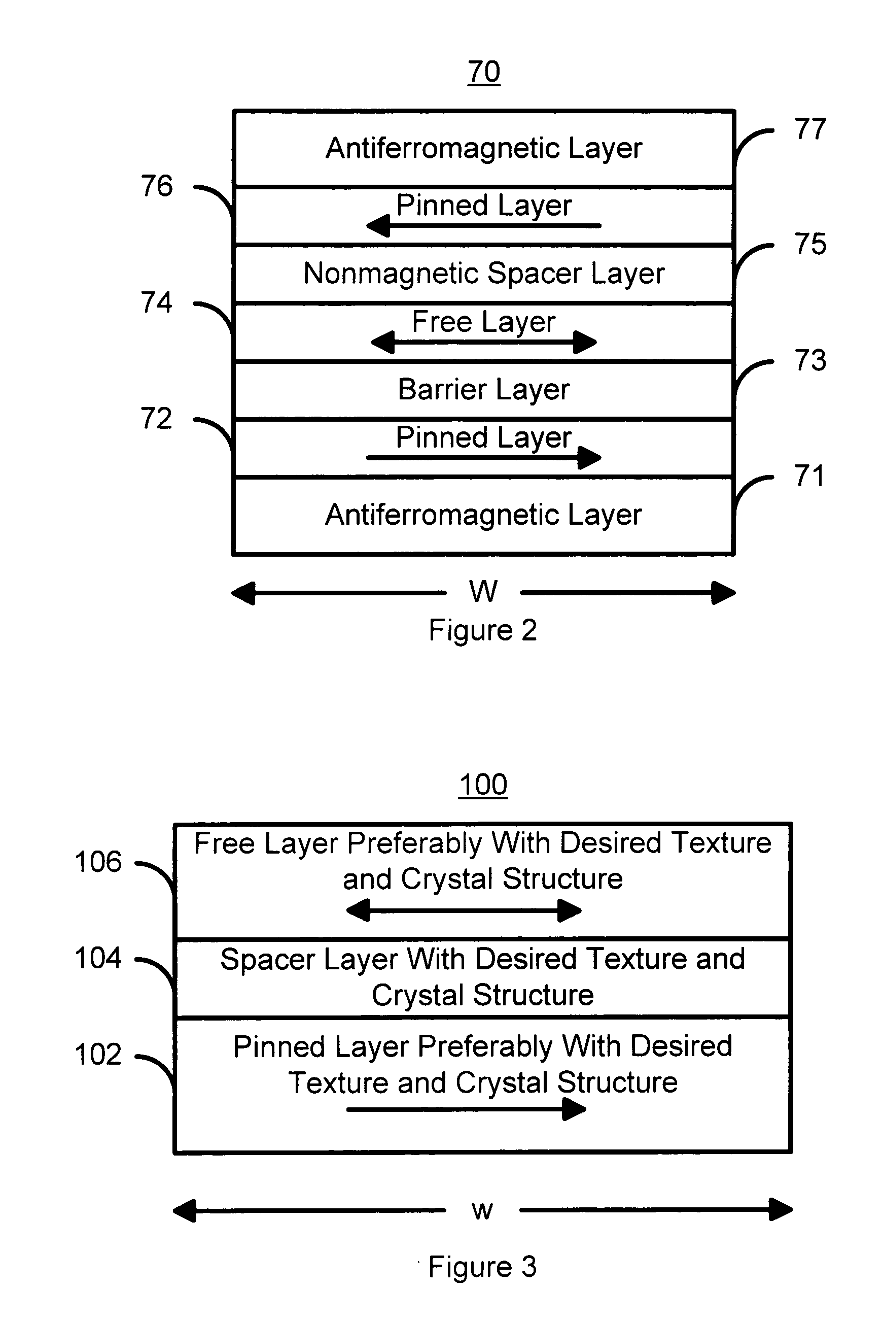
[0032]FIG. 3 is a high-level diagram of a magnetic element 100 in accordance with the present invention and which can be written using spin transfer. The magnetic element 100 includes a pinned layer 102, a spacer layer 104, and a free layer 106. In a preferred embodiment, the magnetic element 100 also includes a pinning layer (not shown) that is preferably an AFM layer. Although depicted as a simple layer, the pinned layer 102 may be a synthetic pinned layer including two ferromagnetic layers separated by a nonmagnetic spacer layer. The thickness of the nonmagnetic spacer layer is configured so that the magnetizations of the ferromagnetic layers are antiferromagnetically coupled. In a preferred embodiment, the pinned layer 102, or the ferromagnetic layer adjacent to the spacer layer 104, has a body centered cubic (bcc) structure. In a preferred embodiment, the pinned layer 102, or the ferromagnetic layer adjacent to the spacer layer 104, has a texture. In a preferred embodiment, thi...

second embodiment

[0049]FIG. 7 is a diagram of a magnetic element 200 in accordance with the present invention and which can be written using spin transfer. The magnetic element 200 is a dual spin filter. The magnetic element 200 includes a first pinned layer 216, an insulating spacer layer 218, a free layer 220, a spacer layer 228, and a second pinned layer 230. The spacer layer 228 is nonmagnetic and either conductive or another insulating tunneling barrier. The magnetic element 200 also preferably includes a first pinning layer 214 and a second pinning layer 232. Also depicted are a bottom contact 212 and a top contact 234. Thus in case of a conducting spacer layer 228, the magnetic element 200 could be considered to include a spin tunneling junction 202 and a spin valve 204 that share a free layer 220. However in case of an insulating tunneling barrier for the spacer layer 228, the magnetic element 200 could be considered to include two spin tunneling junction, 202 and 204, that share a free laye...


PUM


Abstract

A method and system for providing a magnetic element are disclosed. The method and system include providing a pinned layer, a free layer, and a spacer layer between the pinned layer and the free layer. The spacer layer is insulating and has an ordered crystal structure. The spacer layer is also configured to allow tunneling through the spacer layer. In one aspect, the free layer is comprised of a single magnetic layer having a particular crystal structure and texture with respect to the spacer layer. In another aspect, the free layer is comprised of two sublayers, the first sublayer having a particular crystal structure and texture with respect to the spacer layer and the second sublayer having a lower moment. In still another aspect, the method and system also include providing a second pinned layer and a second spacer layer that is nonmagnetic and resides between the free layer and the second pinned layer. The magnetic element is configured to allow the free layer to be switched due to spin transfer when a write current is passed through the magnetic element.

Description

CROSS-REFERENCE TO RELATED APPLICATION [0001] This application is claiming under 35 USC 119(e), the benefit of provisional patent application Ser. No. 60 / 634,013 filed on Dec. 6, 2004.FIELD OF THE INVENTION [0002] The present invention relates to magnetic memory systems, and more particularly to a method and system for providing a magnetic element having an improved signal and that can be switched using a spin transfer effect at a lower switching current. BACKGROUND OF THE INVENTION [0003]FIGS. 1A and 1B depict conventional magnetic elements 10 and 10′. Such conventional magnetic elements 10 / 10′ can be used in non-volatile memories, such as magnetic random access memories (MRAM). The conventional magnetic element 10 is a spin valve and includes a conventional antiferromagnetic (AFM) layer 12, a conventional pinned layer 14, a conventional nonmagnetic spacer layer 16 and a conventional free layer 18. Other layers (not shown), such as seed or capping layer may also be used. The conven...

Claims


Application Information

Patent Timeline
Patent Type & Authority Applications(United States)
IPC IPC(8): H01L21/00
CPCB82Y25/00B82Y40/00H01F10/3254H01F10/3263H01F41/325H01F10/3281H01F41/302H01L43/08H01F10/3272H10N50/10H01L31/00
Inventor PAKALA, MAHENDRAVALET, THIERRYHUAI, YIMINGDIAO, ZHITAO
Owner GRANDIS
Why Eureka
Try Eureka