Magnetic memory bits with perpendicular magnetization switched by current-induced spin-orbit torques

Active Publication Date: 2015-05-14
RGT UNIV OF CALIFORNIA
View PDF2 Cites 71 Cited by
  • Summary
  • Abstract
  • Description
  • Claims
  • Application Information

AI Technical Summary

Benefits of technology

[0019]Symmetry-based analysis of SOT interactions in the base asymmetric structure indicates that the observed bias-field-free switching originates from the lateral symmetry-breaking of the laminate, which gives rise to a new field-like torque (HzFL) upon the application of an in-plane current. The direction of the current-induced effective field corresponding to this field-like SOT is out-of-plane facilitating the switching of perpendicular magnets.
[0020]The structural asymmetry can be engineered in various magnetic heterost

Problems solved by technology

In conventional NM/F/I heterostructures, the form of the resultant current-induced SOT alone does not allow for deterministic switching of a pe

Method used


Image

  • Magnetic memory bits with perpendicular magnetization switched by current-induced spin-orbit torques
  • Magnetic memory bits with perpendicular magnetization switched by current-induced spin-orbit torques
  • Magnetic memory bits with perpendicular magnetization switched by current-induced spin-orbit torques

Examples


example 1

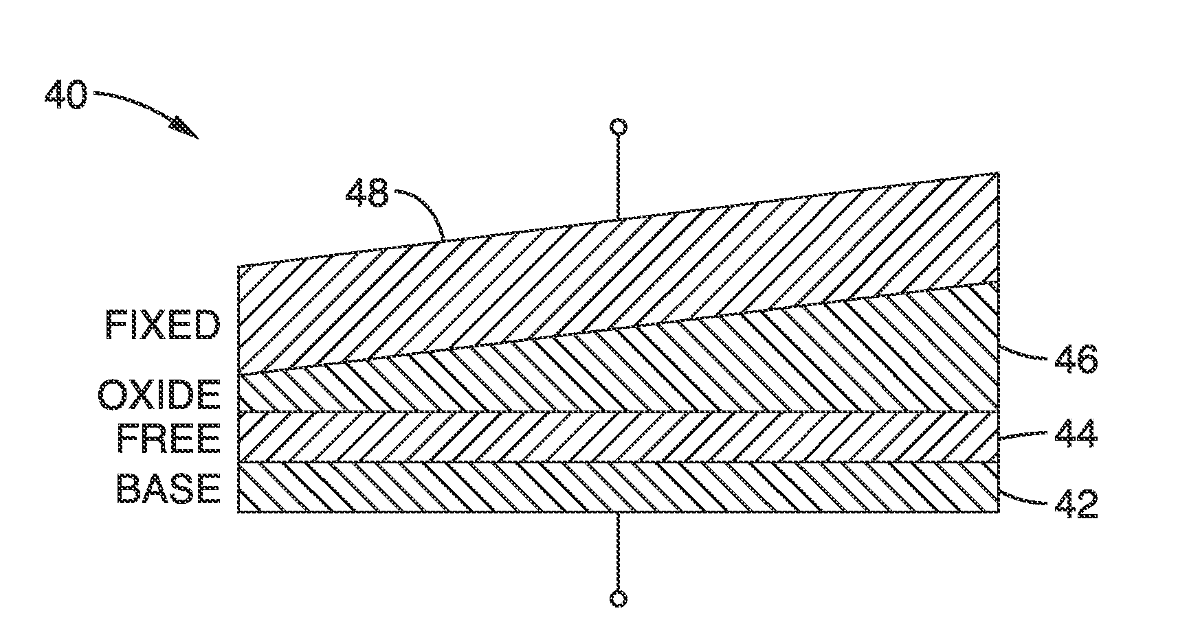
[0085]In order to demonstrate the operational principles of the apparatus and methods, several devices were fabricated and tested. A stack structure of Ta / CoFeB / TaOx was fabricated from Ta(5.0 nm) / Co20Fe60B20(1.0 nm) / Ta(wedge) sputter-deposited films. The metal layers were deposited on a thermally oxidized wafer (on an area of 10 mm×50 mm) by D.C. magnetron sputtering at room temperature, in an AJA international physical vapor deposition system. The deposition rates were 0.06 nm / s for Ta and 0.03 nm / s for Co20Fe60B20 at an argon pressure of 2 mTorr and 3 mTorr, respectively.

[0086]The top oxide layer was formed by first depositing a Ta film as a continuous gradient of thickness along the length of the sample to produce a wedge shape across the wafer. The thickness of the top Ta layer was varied from 0.81 nm to 2.13 nm.

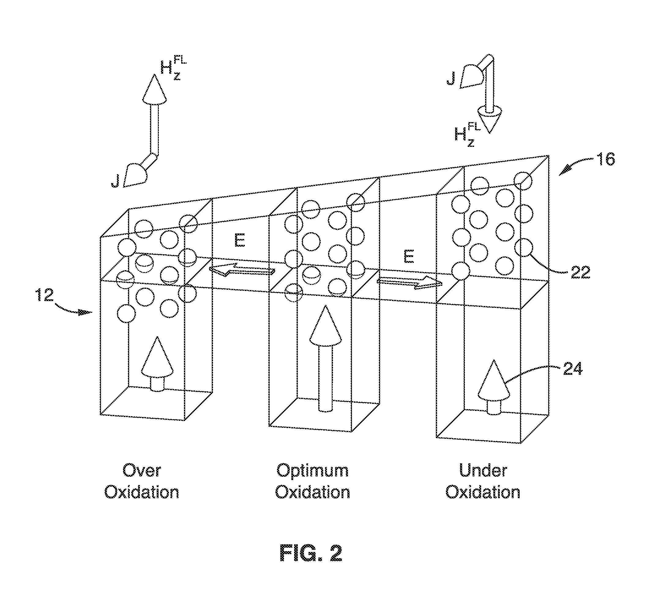
[0087]The TaOx layer was then formed by exposing the sample to radio-frequency O2 / Ar plasma for 100 s to create a Co20Fe60B20 / TaOx interface. Due to the variation of th...

example 2

[0092]To further demonstrate the functionality of the devices, EHE measurements were performed on the Hall bar devices for a set of different direct currents applied along the x-axis. The perpendicular magnetization of Ta / CoFeB / TaOx was measured by EHE, while a current of ±1 mA, ±6 mA, and ±10 mA was applied to the devices.

[0093]EHE signals were measured for the first device (device A, tTa=1.65 nm prior to oxidation) in the dHk / dy>0 region. As expected, small currents had almost no influence on the switching behavior. At larger currents, however, the centers of the hysteresis loops were gradually shifted in the negative direction for currents of a positive polarity, which indicates the presence of a perpendicular effective field, HzFL=HzFLz induced by the current. The value of HzFL can be extracted from the average of the positive (HS+) and negative (HS−) switching fields, i.e. HzFL=−(HS++HS−) / 2. For currents in the opposite direction, the hysteresis loops are shifted in the positiv...

example 3

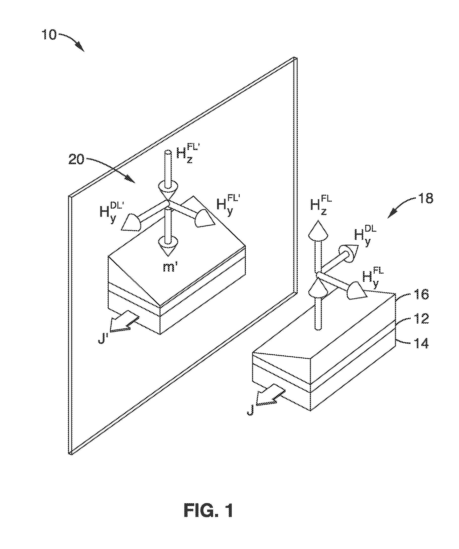
[0099]To further demonstrate the functionality of the apparatus, the selective switching of the magnetization in an out-of-plane magnetized film without the assistance of external magnetic fields was illustrated by manipulation of the perpendicular effective field HzFL induced by an in-plane current along the x-axis of the devices.

[0100]The capability of the apparatus to reversibly switch the perpendicular magnetization was illustrated with currents of ˜6 mA (corresponding to a current density of 5.0×10⁶ A / cm2) for device A (tTa=1.67 nm before oxidation), and by current of ˜3 mA (corresponding to a current density of 2.5×10⁶ A / cm2) for device B. The favored magnetization direction for each current direction is opposite for these two devices, due to the opposite orientations of the current-induced HzFL (i.e. different signs of β). All measurements were carried out at room temperature.

[0101]Perpendicular magnetization as a function of direct current for devices A (tTa=1.67 nm before o...


PUM


Abstract

A basic Spin-Orbit-Torque (SOT) structure with lateral structural asymmetry is provided that produces a new spin-orbit torque, resulting in zero-field current-induced switching of perpendicular magnetization. More complex structures can also be produced incorporating the basic structure of a ferromagnetic layer with a heavy non-magnetic metal layer having strong spin-orbit coupling on one side, and an insulator layer on the other side with a structural mirror asymmetry along the in-plane direction. The lateral structural asymmetry and new spin-orbit torque, in effect, replaces the role of the external in-plane magnetic field. The direction of switching is determined by the combination of the direction of applied current and the direction of symmetry breaking in the device.

Description

CROSS-REFERENCE TO RELATED APPLICATIONS[0001]This application claims priority to, and the benefit of, U.S. provisional patent application Ser. No. 61 / 897,218 filed on Oct. 30, 2013, incorporated herein by reference in its entirety.STATEMENT REGARDING FEDERALLY SPONSORED RESEARCH OR DEVELOPMENT[0002]This invention was made with Government support under HR0011-10-C-0153 awarded by the Defense Advanced Research Projects Agency. The Government has certain rights in the invention.INCORPORATION-BY-REFERENCE OF COMPUTER PROGRAM APPENDIX[0003]Not ApplicableBACKGROUND[0004]1. Technical Field[0005]This technology pertains generally to spin-based nano-electronic devices and systems that use the orbital properties of electrons rather than their charge, and more particularly to laminates producing spin-orbit torques that can switch the magnetization in perpendicularly magnetized laminates without the need for an external magnetic field.[0006]2. Background Discussion[0007]In the emerging technolo...

Claims


Application Information

Patent Timeline
IPC IPC(8): H01L43/02H01L43/12H01L43/10
CPCH01L43/02H01L43/12H01L43/10G11C11/161G11C11/18G11C11/1675H10N52/00H10N50/10
Inventor WANG, KANG L.KHALILI AMIRI, PEDRAMYU, GUOQIANGUPADHYAYA, PRAMEY
Owner RGT UNIV OF CALIFORNIA
Why Eureka
Try Eureka