Ignition coil for use in engine and engine having plastic cylinder head cover

a technology of cylinder head cover and ignition coil, which is applied in the direction of sparking plugs, machines/engines, instruments, etc., can solve the problems of dielectric breakdown, delay in rising, and more output drop, and achieve the effect of light weight structure, vibration of ignition coil, and thin thickness structur

Inactive Publication Date: 2006-06-15
HITACHI LTD +1
View PDF10 Cites 10 Cited by
  • Summary
  • Abstract
  • Description
  • Claims
  • Application Information

AI Technical Summary

Benefits of technology

[0016] It is necessary to thin to the utmost the insulation resin which is filled up between the secondary bobbin and the center core, for example the soft epoxy resin is used as stated in the above, to secure the secondary bobbin thickness (to secure the insulation performance). Such a secondary bobbin thickness is desirable to secure at the minimum of 0.1 mm to guarantee a linear thermal expansion difference absorption (the heat shock mitigation) against the center core and the secondary bobbin and the absorption in the size scattering in a mass production of a bobbin material and the core and a smoothness of the vacuum potting.
[0056] Under the above stated knowledge, the present invention is constituted, according to the construction, the head cover of the engine is made of the plastic material, in a case where this head cover is installed to the individual ignition type ignition coil, the center of the gravity of the ignition coil is positioned at a low position of the engine head cover, and further the comparative light weight circuit case having the connector in the pencil type coil is fixed (for example, the screw fixing) to the outer face of the plastic head cover, and at this fixing portion and the plug hole combination position of the plug hole two point support mechanism of the axial direction can be obtained. As a result, the vibration of a whole ignition coil is made small and further the vibration of the ignition coil which is given to the plastic head cover can be restrained, the light weight structure (the thin thickness structure) and simplification of the plastic head cover can be attained, and further the mount of the individual ignition type ignition coil can be realized.

Problems solved by technology

A secondary voltage output and a secondary voltage rising speed are affected by the electrostatic floating capacitance and the more the electrostatic floating capacity becomes large, the more the output lowers and a delay in the rising generates.
In the case of the structure in which the secondary wire is arranged inside the primary wire, in the structure between the secondary bobbin and the center core, it is an important problem that how an anti-heat shock performance and a mitigation of electric field concentration are compatible with.
However, in the case where the resin is filled up between the secondary bobbin and the center core, according to a difference between the coefficient of linear thermal expansion (13×10−6 mm / ° C.) of the center core and the coefficient of linear thermal expansion of the resin, there is an axioms that cracks cause in the resin and the dielectric break down generates.
However, in the above case, a flowability of a resin molding lowers and in particularly there is a problem that it is difficult to pot the resin to a gap (one figure level mm at a decimal point) between the center core and the secondary bobbin which is a minute clearance.

Method used


Image

  • Ignition coil for use in engine and engine having plastic cylinder head cover
  • Ignition coil for use in engine and engine having plastic cylinder head cover
  • Ignition coil for use in engine and engine having plastic cylinder head cover

Examples


first embodiment

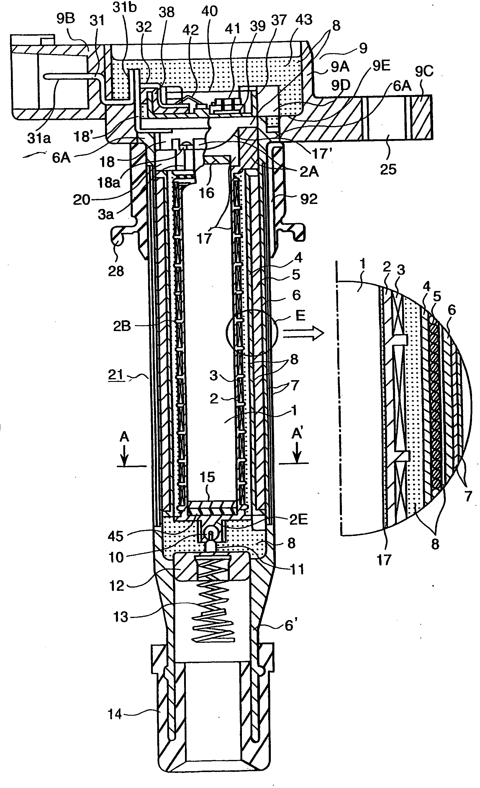
[0087] First of all referring to FIG. 1-FIG. 21 an ignition coil (so called a secondary wire being arranged inside primary wire structure pencil type coil) will be explained.

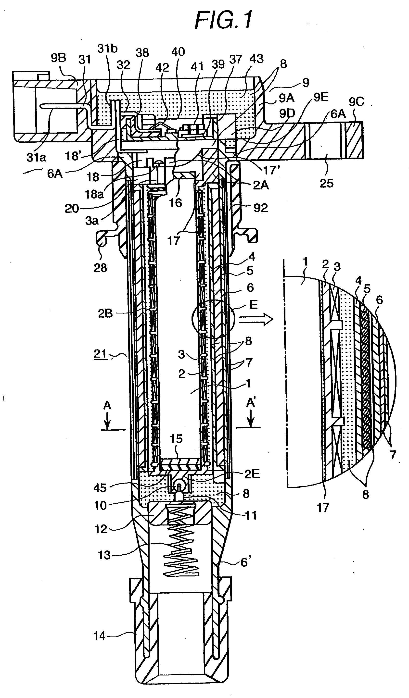
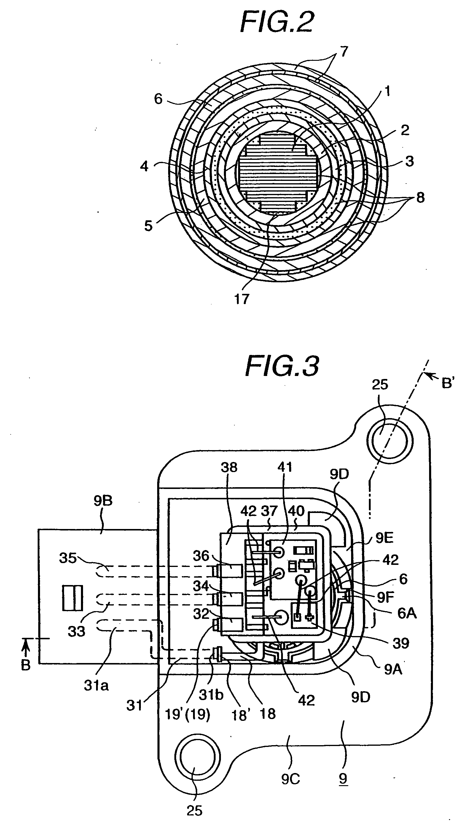
[0088]FIG. 1 is a longitudinal cross-sectional view (B-B′ line cross-sectional arrow viewing view of FIG. 3) of an ignition coil 21 and E portion enlargement cross-sectional view of a part of thereof, FIG. 2 is A-A′ line cross-sectional view of FIG. 1. FIG. 3 is a view taken from an upper face of the ignition coil of FIG. 1 and shows an interior portion of a circuit case 9 by expressing a condition of before a resin (silicone gal) fill-up.

[0089] In an interior portion of a long and narrow cylindrical shape coil case (an outer case) 6, extending over from a center portion (an inner side) toward an outer side a center core 1, a secondary bobbin 2, a secondary coil 3, a primary bobbin 4, and a primary coil 5 are arranged in order. Further, in the secondary bobbin 2 in a gap between the center core 1 and the second...

second embodiment

[0219] Next, a second embodiment according to the present invention will be explained referring to from FIG. 22 to FIG. 29.

[0220]FIG. 22 is a partially cross-sectional view (D-D′ line cross-sectional view of FIG. 23) of an ignition coil according to the second embodiment. In this figure, the same ones of the reference numerals used in the first embodiment indicate the same ones or the common elements. FIG. 18 is a view taken from an upper face of the ignition coil of FIG. 17 and expresses a condition before the resin fill-up of the interior portion of the circuit case. Further, F-F′ line cross-section view of FIG. 22 is omitted because this view is the similar to FIG. 2.

[0221] In this embodiment, the main differences which differ from the first embodiment will be stated.

[0222] An ignition noise prevention use capacitor 71 (hereinafter, it is called as the noise prevention capacitor 71) in this embodiment is mounted in an interior portion of the circuit case 9. As a result, in addi...


PUM

PropertyMeasurementUnit
temperatureaaaaaaaaaa
young's modulusaaaaaaaaaa
thicknessaaaaaaaaaa

Abstract

A long and narrow shape independent ignition type ignition apparatus has a long and narrow shape center core for an internal combustion engine. At least one of magnet member and a rubber material member is arranged at an end portion of the center core. A circumference of the center core including said magnet member and said rubber material member is surrounded using a soft material member.

Description

TECHNICAL FIELD [0001] The present invention relates to an individual coil type ignition coil for use in an engine which is prepared for every ignition coil each of an engine and is used by directly connecting to said respective ignition coil and an engine having a plastic head cover which is related technically to those ignition coils. BACKGROUND ART [0002] Recently, an individual ignition coil type ignition coil for use in an engine has developed such an ignition coil is individually and directly connected to each of the ignition coils which are introduced to plug holes of the engine. In this kind of the ignition coil, a distributor becomes unnecessary, as a result at the distributor and a high tension cord for the distributor etc. a supply energy for the ignition coil does not fall down. In addition to these, without a consideration about a fall down of the ignition energy, it can design the ignition coil. Accordingly, a coil capacity can be made small and a small scale structure...

Claims


Application Information

Patent Timeline
Patent Type & Authority Applications(United States)
IPC IPC(8): G06F11/00F02P3/02F02P3/04F02P13/00H01F27/32H01F38/12H01T13/44
CPCF02D2400/18H01T13/44F02P3/0435F02P11/00F02P13/00H01F27/022H01F27/29H01F27/325H01F27/327H01F27/40H01F38/12H01F41/0612H01F2005/025H01F2038/122H01F2038/125H01F2038/127F02P3/02H01F41/064F02P15/00
Inventor SHIMADA, JUNICHISUGIURA, NOBORUANZO, YOICHIKONDO, EIICHIROKOBAYASHI, KAZUTOSHIKOSAI, TAKAHIDEUEDA, TOSHIAKI
Owner HITACHI LTD
Why Eureka
Try Eureka