Programming language model generating apparatus for hardware verification, programming language model generating method for hardware verification, computer system, hardware simulation method, control program and computer-readable storage medium

a programming language model and hardware verification technology, applied in the direction of instrumentation, program control, cad circuit design, etc., can solve the problems of increasing the calculation amount required for simulation, poor calculation efficiency, and increasing the time required for simulation, so as to achieve efficient verification, reduce cost, and improve efficiency

Inactive Publication Date: 2006-06-15
SHARP KK
View PDF3 Cites 18 Cited by
  • Summary
  • Abstract
  • Description
  • Claims
  • Application Information

AI Technical Summary

Benefits of technology

[0044] As described above, according to the present invention, it is possible to verify the hardware at a cycle accurate level at a lower cost and at a higher speed, compared to verification using a conventional HDL simulator. Further, when the verification of hardware and software is performed cooperatively, the verification of the hardware can be performed using a model described in a general-purpose programming language. Accordingly, it is possible to efficiently perform the verification at a cycle accurate level without using any debugger in the different language.
[0045] According to the present invention, it is possible to improve the efficiency of debugging the hardware by observing the state of the registers and the storage device within the hardware at an arbitrary clock cycle.
[0046] According to the present invention, a model is generated using the control / data flow graph. It is not necessary to generate data path information which is performed after the scheduling process is completed in a higher-order synthesis process. Accordingly, it is possible to greatly reduce the computing time required for generating an operation model, even when the scale of the circuit becomes large.
[0047] As described above, according to the present invention, it is possible to shorten the TAT for designing and / or developing an LSI and to reduce the cost required for the development.

Problems solved by technology

However, the conventional technology described above provides the following problems.
Accordingly, there is a problem that there are many redundant and unnecessary calculations and the efficiency of the calculation is poor in verifying the hardware at a cycle accurate level.
Further, when the scale of a circuit to be simulated becomes large or the test pattern becomes long, a calculation amount required for the simulation is increased.
This causes a problem that the time required for the simulation is increased.
Further, there is a problem that the HDL simulator is expensive and the cost required for developing a system LSI is increased.
This causes a problem that the efficiency of the verification is reduced.
Further, in the conventional technology disclosed in Reference 1, it is possible to perform a verification at an algorithm level, but impossible to perform a verification at a cycle accurate level.
Accordingly, it is impossible to verify whether or not the hardware satisfies the specification required for the given system, such as an operation frequency.
This causes a problem that the efficiency of the verification is reduced.
Thus, in the conventional technologies described above, there is a problem that TAT (turnaround time, i.e., the time required for turning back when a problem occurs and solving the problem) in designing and / or developing an LSI is prolonged and the cost required for the development is increased.

Method used


Image

  • Programming language model generating apparatus for hardware verification, programming language model generating method for hardware verification, computer system, hardware simulation method, control program and computer-readable storage medium
  • Programming language model generating apparatus for hardware verification, programming language model generating method for hardware verification, computer system, hardware simulation method, control program and computer-readable storage medium
  • Programming language model generating apparatus for hardware verification, programming language model generating method for hardware verification, computer system, hardware simulation method, control program and computer-readable storage medium

Examples


Embodiment Construction

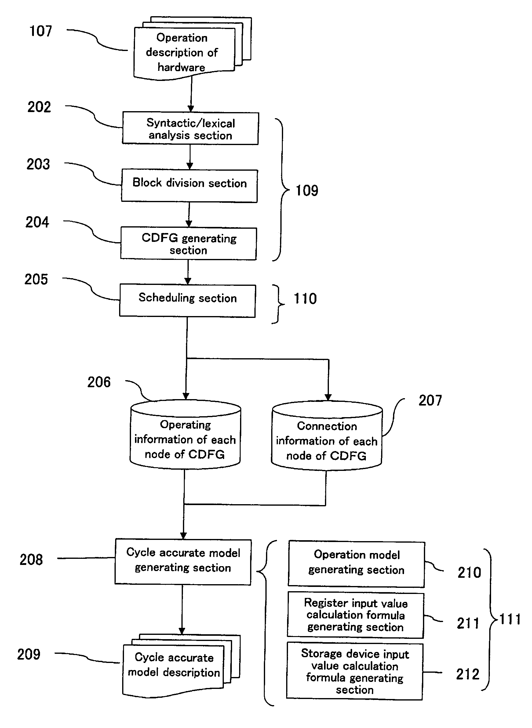
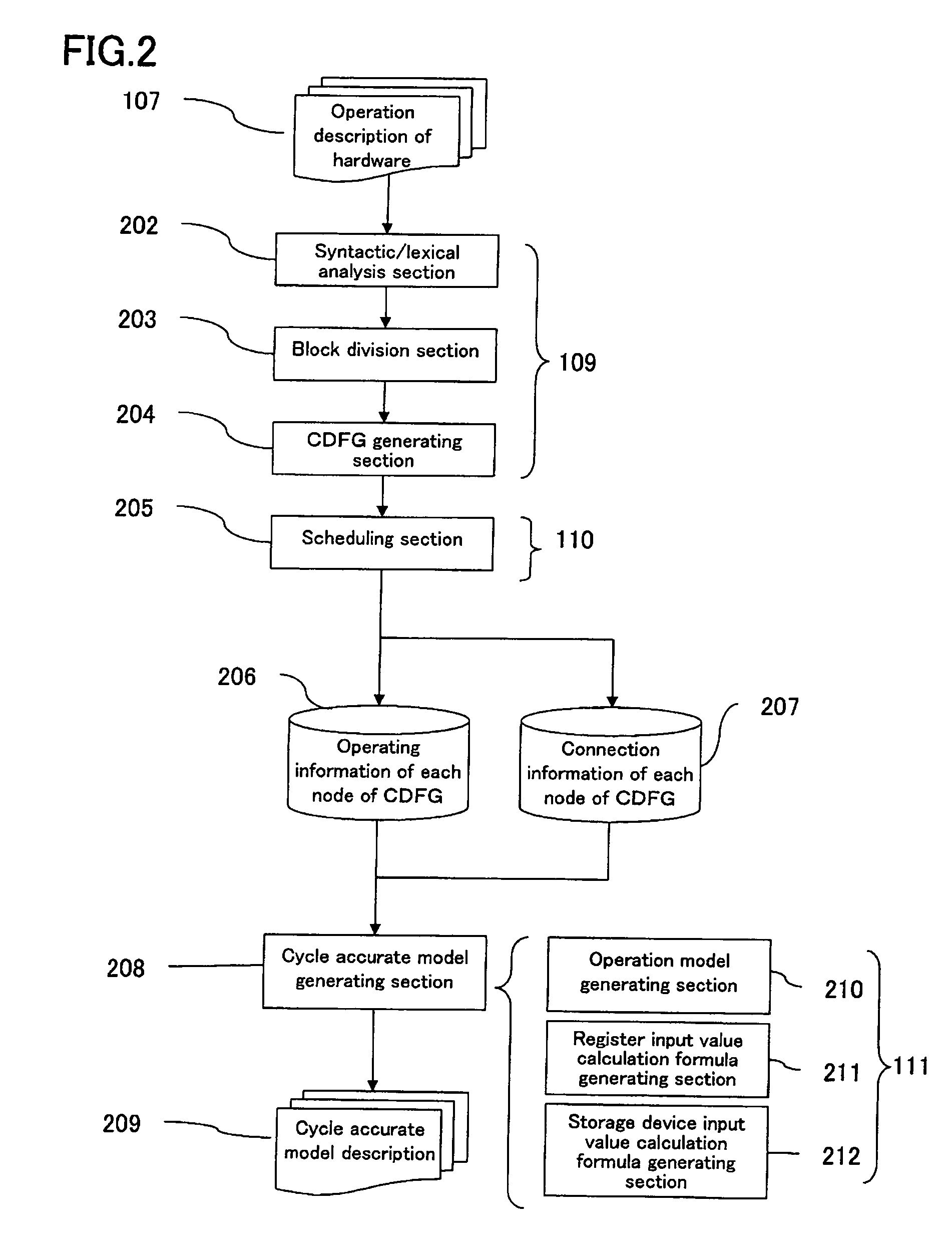
[0069] The following describes in detail an embodiment of a programming language model generating apparatus for hardware verification and a programming language model generating method for hardware verification according to the present invention, with reference to the drawings.

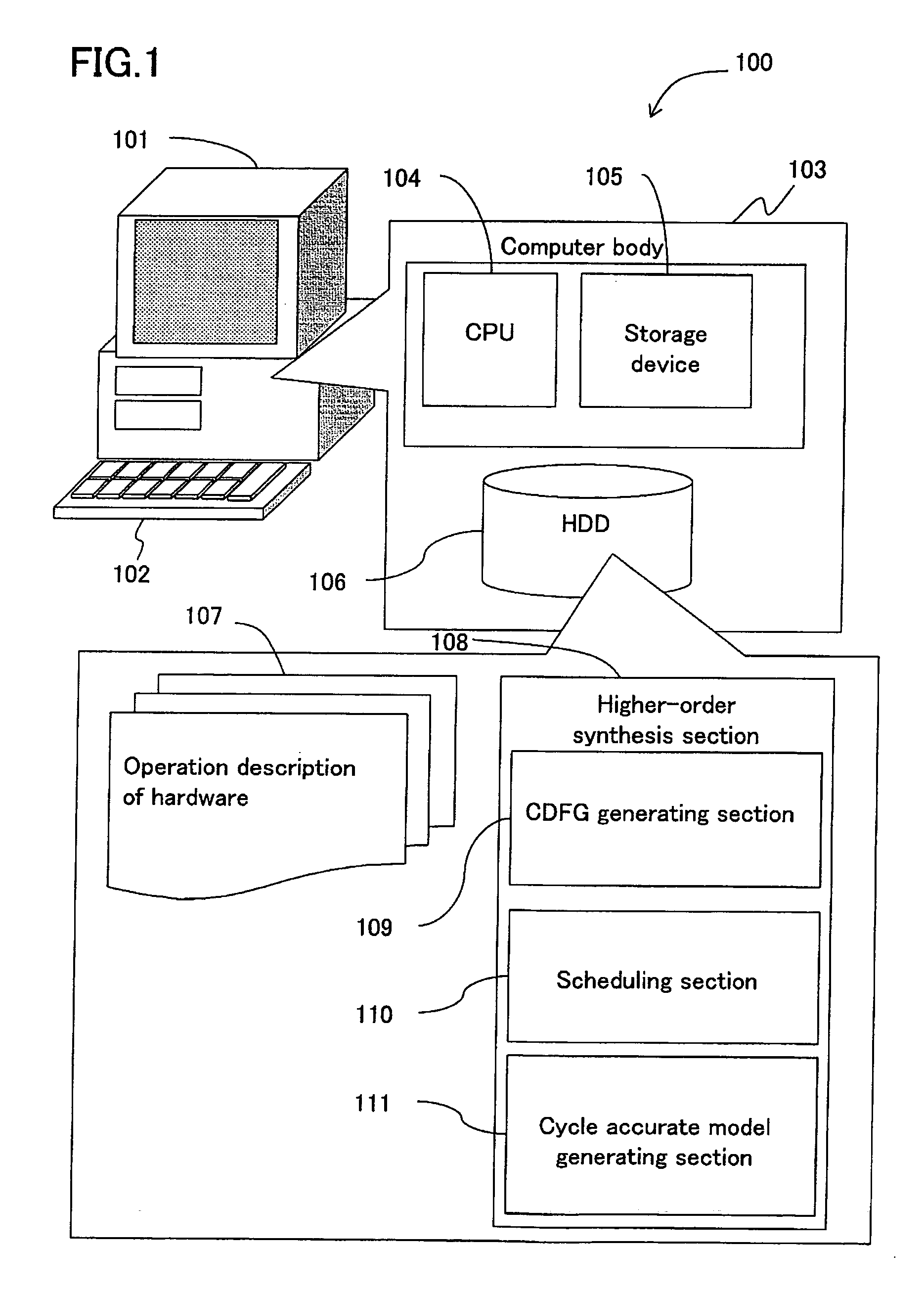
[0070]FIG. 1 shows an exemplary configuration of a computer system used to implement a programming language model generating apparatus for hardware verification according to an embodiment of the present invention.

[0071] In FIG. 1, a computer system 100 functions as a programming language model generating apparatus for hardware verification. The computer system 100 includes a monitor device 101 as an output device, an input device 102 such as a keyboard, and a computer body 103. The computer body 103 includes a CPU (Central Processing Unit) 104 as a control section, a storage device 105 such as a work memory, and a computer-readable storage medium 106 such as a magnetic disc (e.g. FD), an optical disc (e.g. C...


PUM


Abstract

The CDFG is generated by the CDFG generating section 109 based on the operation description of hardware 107, the CDFG is scheduled by the scheduling section 110 at an operation frequency required as the specification of the hardware and is assigned to each state, and the operation model of the hardware is generated by the cycle accurate model generating section 111 for each state as a description represented by a general-purpose programming language. The model which can be simulated for each state is generated by generating the operation model of each node using the operation information of the nodes included in the CDFG, and by determining the order in which the operation model of each node is calculated using the connection information of the nodes. As a result, it is possible to generate a model for verification described in a general-purpose programming language, which is capable of verifying hardware at a cycle accurate level at a lower cost and at a higher speed, with a smaller amount of calculation compared with the conventional method.

Description

[0001] This Non provisional application claims priority under 35 U.S.C. §119(a) on Patent Application No.2004-331229 filed in Japan on Nov. 15, 2004, the entire contents of which are hereby incorporated by reference. BACKGROUND OF THE INVENTION [0002] 1. Field of the Invention [0003] The present invention relates to a programming language model generating apparatus for hardware verification for automatically generating a general-purpose programming language description capable of verifying the hardware; a programming language model generating method for hardware verification using the apparatus; a computer system; a hardware simulation method using the computer system; a control program for making a computer execute the method; and a computer-readable storage medium having the control program stored thereon. [0004] 2. Description of the Related Art [0005] In the development of a system LSI, it is necessary to verify whether or not the operation of a designed hardware satisfies the s...

Claims


Application Information

Patent Timeline
Patent Type & Authority Applications(United States)
IPC IPC(8): G06F9/45
CPCG06F17/5045G06F30/30
Inventor MORISHITA, TAKAHIROOKADA, KAZUHISA
Owner SHARP KK
Why Eureka
Try Eureka