Energy device and various applications using the same
a technology of energy devices and capacitors, applied in the direction of capacitor collector combinations, electrochemical generators, cell components, etc., can solve the problems of marked degradation of input/output characteristics and low energy density of capacitors involved, and achieve excellent input/output characteristics
- Summary
- Abstract
- Description
- Claims
- Application Information
AI Technical Summary
Benefits of technology
Problems solved by technology
Method used
Image
Examples
example 1
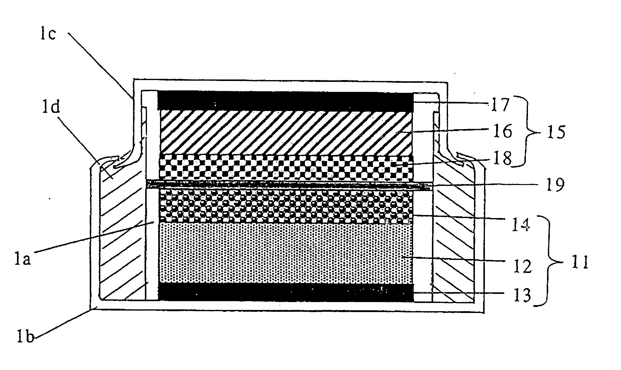
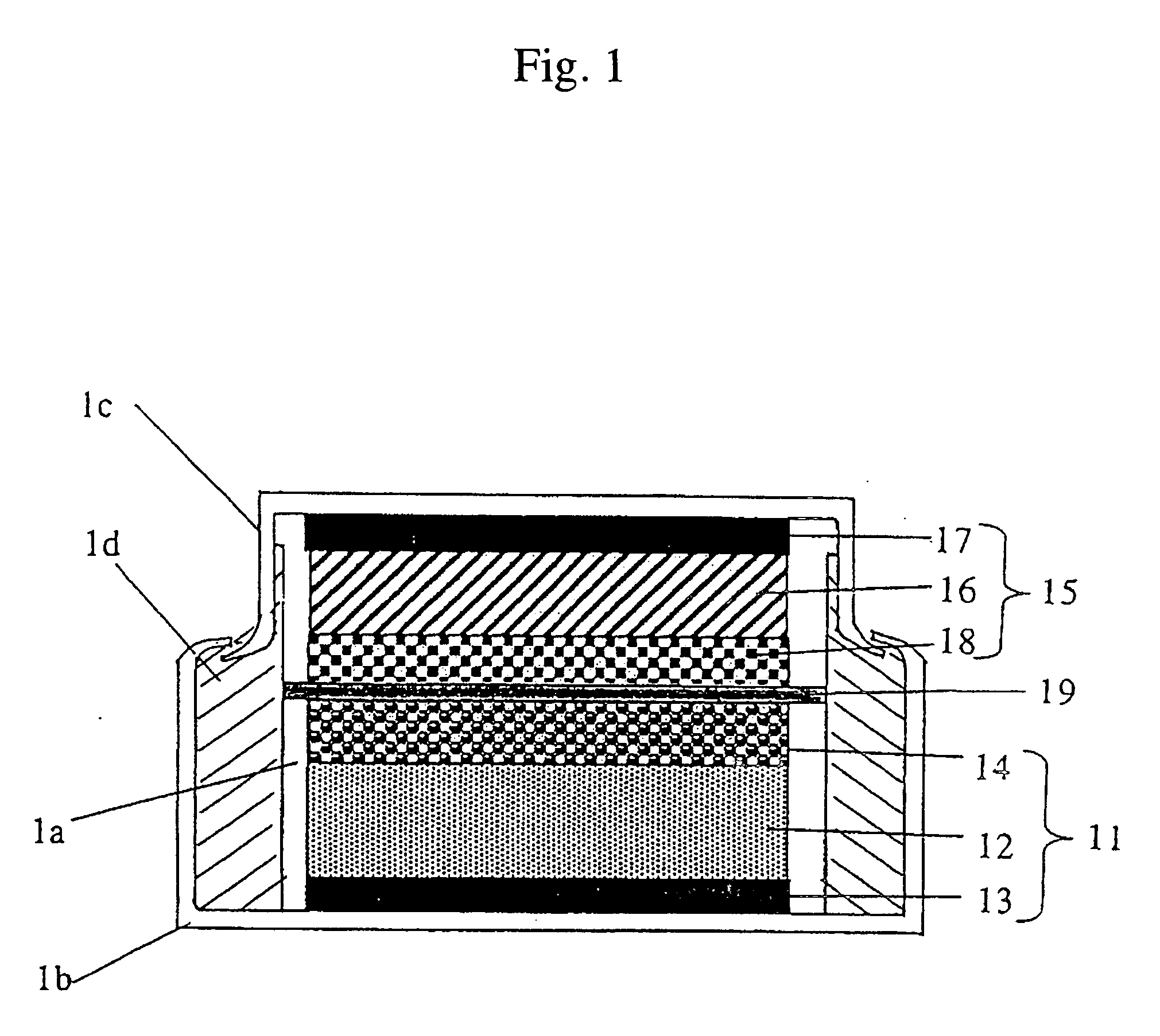
[0109] The coin-shaped energy device shown in FIG. 3 was fabricated. The positive electrode faradic layer 12 was fabricated in the following manner. The positive electrode active material was Li1.05Mn1.95O4 having an average particle size of 10 μm, and a conducting aid obtained by mixing graphite carbon having an average particle size of 3 μm and a specific surface area of 13 m2 / g and carbon black having an average particle size of 0.04 μm and a specific surface area of 40 m2 / g so as to have a weight ratio of 4:1 was used. Using as a binder a solution obtained by dissolving 8 wt % of polyvinylidene fluoride in N-methylpyrolidone in advance, the positive electrode active material, the conducting aid and polyvinylidene fluoride were mixed so as to have a weight ratio of 85:10:5 and sufficiently kneaded to form a positive electrode slurry. This positive electrode slurry was applied to a one surface of the positive current collector 13 composed of an aluminum foil having a thickness of ...
example 2
[0113] An energy device was fabricated in the same manner as in Example 1 except that the weight ratio of the positive electrode active material, the conducting aid, polyvinylidene fluoride and activated carbon was 74:10:6:10 based on the total weight of the positive electrode 12 and the positive electrode non-faradic layer 14, and the activated carbon contributed to a charge adsorption reaction and had a specific surface area of 2000 m2 / g and a weight of 10 wt % for forming a predetermined region in the energy device of Example 1. The specific surface area of the activated carbon is preferably 2000 to 5000 m2 / g.
example 3
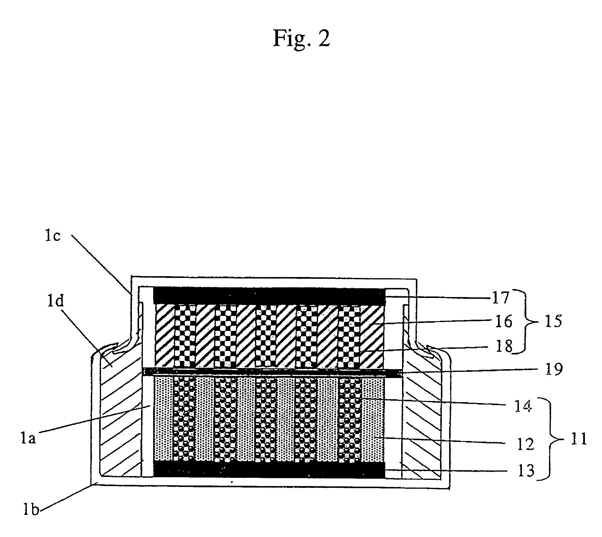
[0128]FIG. 8 is a sectional view of the coin-shaped energy device according to the present invention. The positive electrode faradic layer 12 was applied to one surface of the positive electrode current collector 13 composed of an aluminum foil having a width of 1 mm and a thickness of 20 μm using the positive electrode slurry of Comparative Example 1, provided with uncoated areas at intervals of 1 or 2 mm, and dried. Activated carbon having a specific surface area of 2000 m2 / g and carbon black having an average particle size of 0.04 μm and a specific surface area of 40 m2 / g were mixed so as to have a weight ratio of 8:1, and using as a binder a solution obtained by dissolving 8 wt % of polyvinylidene fluoride in N-methylpyrolidone in advance, activated carbon, carbon black and polyvinylidene fluoride were mixed so as to have a weight ratio of 80:10:10 and sufficiently kneaded to form a slurry. This slurry was applied to the uncoated areas of a positive electrode current collector 1...
PUM
| Property | Measurement | Unit |
|---|---|---|
| temperatures | aaaaa | aaaaa |
| temperatures | aaaaa | aaaaa |
| diameter | aaaaa | aaaaa |
Abstract
Description
Claims
Application Information
 - R&D
- Intellectual Property
- Life Sciences
- Materials
- Tech Scout
- Unparalleled Data Quality
- Higher Quality Content
- 60% Fewer Hallucinations
Browse by: Latest US Patents, China's latest patents, Technical Efficacy Thesaurus, Application Domain, Technology Topic, Popular Technical Reports.
© 2025 PatSnap. All rights reserved.Legal|Privacy policy|Modern Slavery Act Transparency Statement|Sitemap|About US| Contact US: help@patsnap.com


