Stratified flow chemical reactor

a chemical reactor and flow flow technology, applied in lighting and heating apparatus, mixers, stationary tubular conduit assemblies, etc., can solve the problems of undesirable products in the reactor, inability to compensate for the low conductivity of a polymer reaction mixture, and limiting heat transfer in the reactor design

Inactive Publication Date: 2003-07-17
SAUDI BASIC IND CORP SA
View PDF12 Cites 52 Cited by
  • Summary
  • Abstract
  • Description
  • Claims
  • Application Information

AI Technical Summary

Problems solved by technology

In the case of certain polymerization reactions, due to the low conductivity and high viscosity of the reaction mixture, heat transfer is a limiting factor in reactor design.
Further, it is frequently not possible to compensate for the low conductivity of a polymer reaction mixture by using lower coolant temperatures because low coolant temperatures cause polymer solidification in the reactor.
In many polymer reactors, the poor heat transfer characteristics of polymer reaction mixture results in poor reaction temperature control resulting in the formation of undesirable products in the reactor.
This negatively affects the flow and mechanical properties of the desired polymer end product.
The construction of the internal coils required by such reactors is extremely labor intensive and therefore very costly.
Further, the internal heat transfer coils employed in such reactors have a history of failure causing polymer to be contaminated with heat transfer oil.
Despite the agitation in these reactors, the heat transfer characteristic of wiped-film reactors is nevertheless poor and hot spots frequently develop in such reactors.
Using the vaporization of volatile monomer reactants to remove the heat reaction from a polymer reaction mixture is generally not workable when the polymer reaction involves the co-polymerization of more than one monomer.
In such cases, the vaporization of the different monomers is generally not equal causing uncontrolled concentration of the different co-monomers.
The inclusion of a mechanical agitator in a polymer reactor is often an unwanted necessity to improve heat transfer and homogeneity.
These devices are costly, require much maintenance and can cause quality problems because the agitator shaft seal is often a source of air ingress to a reactor, which can generate undesirable oxidation by-products such as aldehydes and ketones.
These compounds can retard a polymerization reaction and can cause product discoloration.
The temperature in such reactor is usually well controlled, however, the volume occupied by the annular plates and tubes in the reactor reduce available reactor volume significantly.
However, such reactions must generally proceed at low temperature due to the extreme reactivity of the reactants.
However, the effectiveness of cooling jackets on anionic polymerization reactors is constrained by the low heat transfer coefficients applying of the convection mechanism and by the limited range of coolant temperature imposed by polymer solidification temperatures.
Convection heat transfer is limited by many factors, including the velocity of the heat transfer fluid, the temperature differential between the reaction mixture and the cooling fluid, the viscosity of the heat transfer fluids, the surface area available for heat transfer, the materials of construction of the heat transfer device and the condition of the heat transfer surfaces, i.e., whether they are fouled.
Conventional evaporative cooling from a submerged heat transfer surface enjoys higher heat transfer coefficients than convection cooling, but is limited by the liquid phase surrounding the submerged tubes.
Isothermal reactors are particularly required when the rate of reaction is high (such as in anionic polymerization) or when the rate of heat removal is low (due to high viscosity, poor heat conductivity or low velocity).

Method used


Image

  • Stratified flow chemical reactor
  • Stratified flow chemical reactor
  • Stratified flow chemical reactor

Examples


Embodiment Construction

[0066] The following example illustrates the efficacy of the reactors of the invention to maintain essentially isothermal conditions in chemicals and especially polymerization reactions.

[0067] Polystyrene mass polymerization technologies are differentiated by the configuration of the main polymerization reactors used to bring conversion from 30% to 45% solids to 65% to 85% solids. During the course of the polymerization reaction large amounts of heat is evolved. If this heat of reaction is not removed, the reactor temperature will increase causing an unwanted and uncontrolled spread of the polymer molecular weight which adversely affects polymer properties.

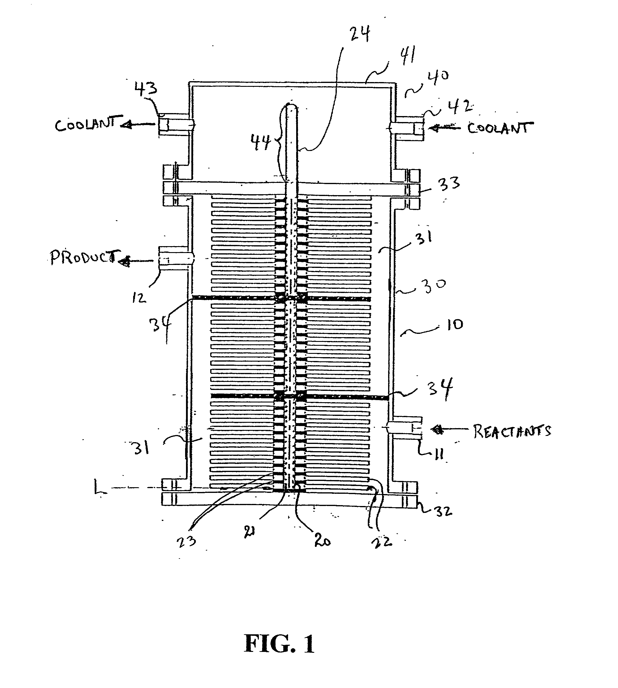
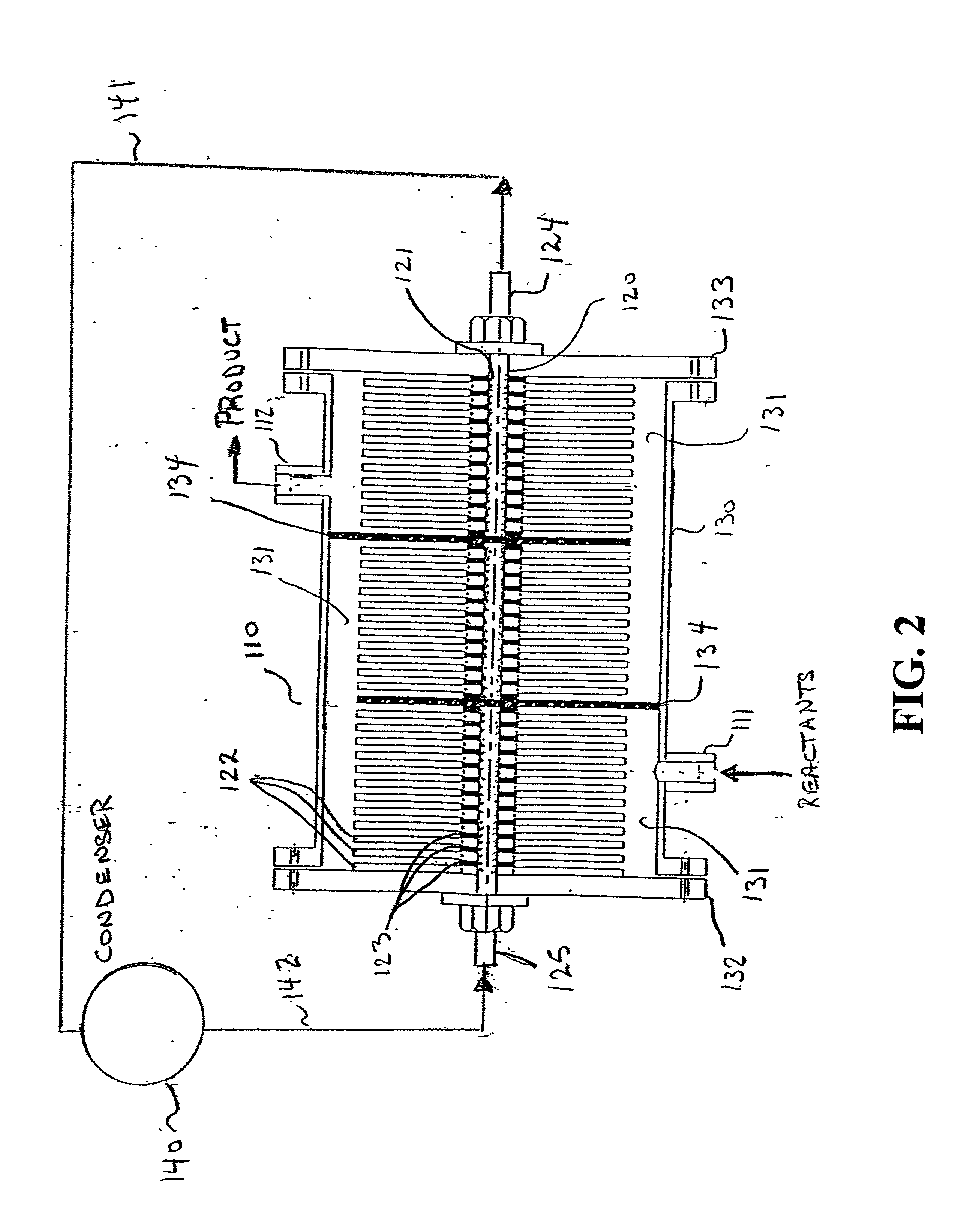
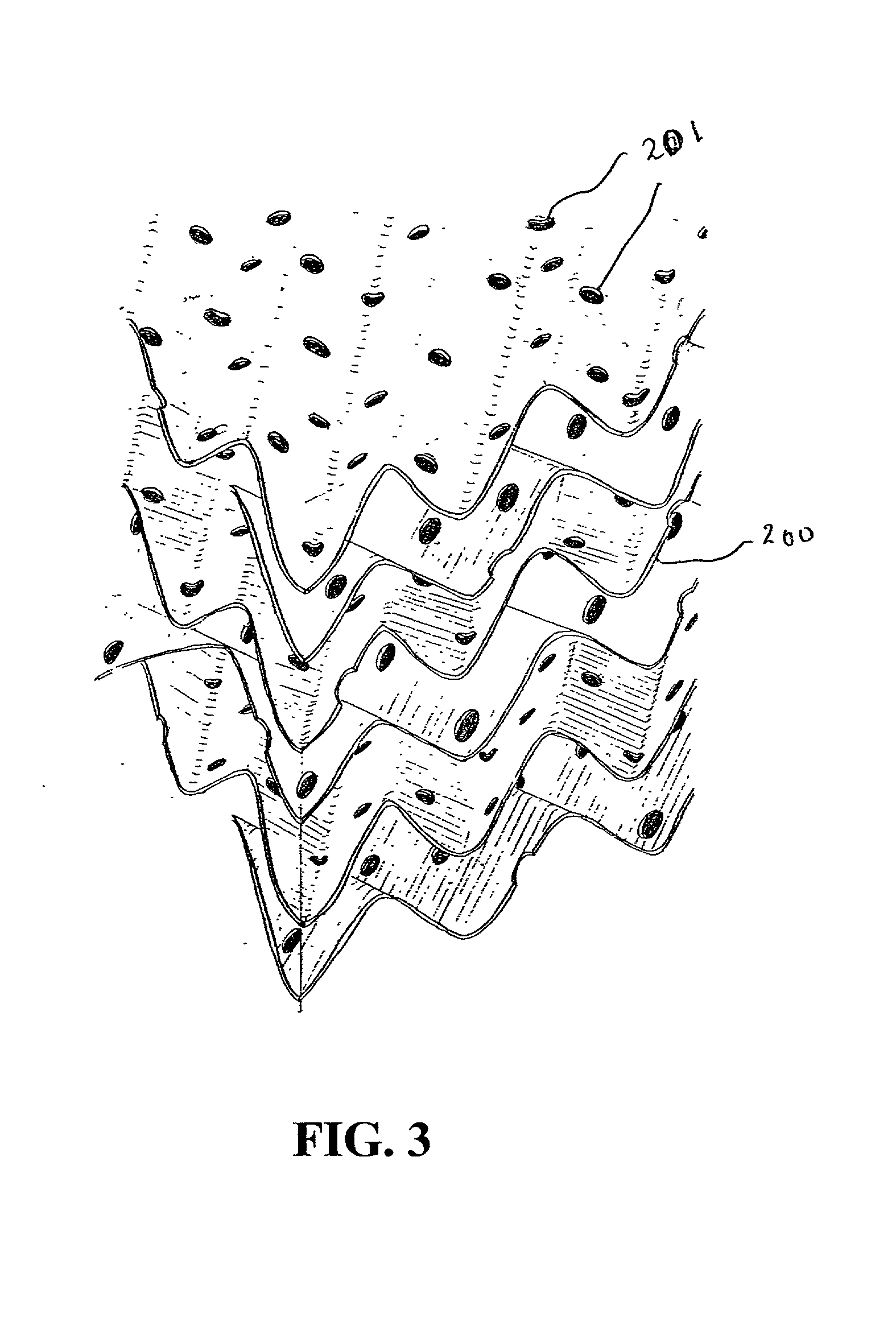
[0068] A polystyrene mass polymerization is conducted in a reactor according to the invention consisting of a jacketed vertical pipe containing several straight heat pipes onto which are fitted a number of fins. The inside of the heat pipes is covered with a porous medium from which a heat transfer fluid is vaporized to provide co...


PUM


Abstract

A polymerization reactor for exothermic liquid phase reactions comprises a reaction zone which is divided into a plurality of channels by thermally conductive heat transfer fins which are conductively mounted on one or more heat pipes for the removal of heat of reaction from reactants and reaction products flowing between the heat transfer fins. The reactor of the invention is capable of maintaining essentially isothermal conditions without the use of complicated and maintenance intensive agitators. The reactor is particularly useful when viscosity of the reactants and/or reaction products is high, when the reaction conducted has a fast reaction rate and when consistent polymer properties are desired.

Description

[0001] 1. Field of the Invention[0002] The present invention relates to an improved chemical reaction apparatus which is capable of removing large heat fluxes from a viscous reaction mixture while maintaining the reaction mixture at essentially isothermal conditions. The invention also relates to a method of conducting chemical reactions, and in particular, polymerization reactions, at essentially isothermal conditions using the novel reactor of the invention.[0003] 2. Description of Related Art[0004] A variety of commercially important chemical reactions, and in particular polymerization reactions, require that reactants be maintained within a narrow temperature range to achieve desired product properties.[0005] In the case of certain polymerization reactions, due to the low conductivity and high viscosity of the reaction mixture, heat transfer is a limiting factor in reactor design. Further, it is frequently not possible to compensate for the low conductivity of a polymer reaction...

Claims


Application Information

Patent Timeline
Patent Type & Authority Applications(United States)
IPC IPC(8): B01F5/06B01F15/06B01J19/00B01J19/24B01J19/32F28D15/02F28D15/04F28F1/32
CPCB01F5/0603F28F1/32B01J19/0013B01J19/24B01J19/32B01J2219/00081B01J2219/00085B01J2219/00094B01J2219/00768B01J2219/00777B01J2219/182B01J2219/185F28D15/0233F28D15/0275F28D15/04B01F15/066B01F25/421B01F35/93
Inventor LE, VINH N.
Owner SAUDI BASIC IND CORP SA
Why Eureka
Try Eureka