Device for determining thoracic impedance

a technology of thoracic impedance and device, which is applied in the field of electromechanical implants, can solve the problems of insufficient consideration of the inability to determine the absolute value of the measured impedance, and the inability to achieve long-term changes in the measured impedance value, so as to achieve the effect of reliable determination of the pulmonary impedan

Active Publication Date: 2006-06-22
BIOTRONIK SE & CO KG
View PDF13 Cites 118 Cited by
  • Summary
  • Abstract
  • Description
  • Claims
  • Application Information

AI Technical Summary

Benefits of technology

[0008] With a view to the state of the art, it is thus an aspect of the invention to present a device which makes it possible to more reliably determine pulmonary impedance irrespective of other long-term changes.

Problems solved by technology

The body reacts to the heart's reduced pumping capacity by means of compensation mechanisms which, however, in the long term result in progressive deterioration of the cardiac state.
However, it is not sufficient to consider the absolute value of the measured impedance because the impedance to a large extent depends on the patient's anatomy and on the quality of the contact between the cardiac pacemaker electrode and the body tissue.
However, the device described in U.S. Pat. No. 5,957,861 is associated with a disadvantage in that long-term changes in the measured impedance values can also occur due to other causes, e.g. scarring (cicatrisation) of the tissue surrounding the cardiac pacemaker and the cardiac pacemaker electrode, or a change in the cardiac geometry due to advancing cardiac insufficiency.
Without home monitoring, the physician can only obtain this information within the framework of examining the patient.
In critical situations, this would lead to undesirable delays in the flow of information.
Furthermore, any examination involves a significant investment in time, both to the physician and to the patient.
Frequent investigation impairs the patient's mobility and quality of life.

Method used


Image

  • Device for determining thoracic impedance
  • Device for determining thoracic impedance
  • Device for determining thoracic impedance

Examples


Embodiment Construction

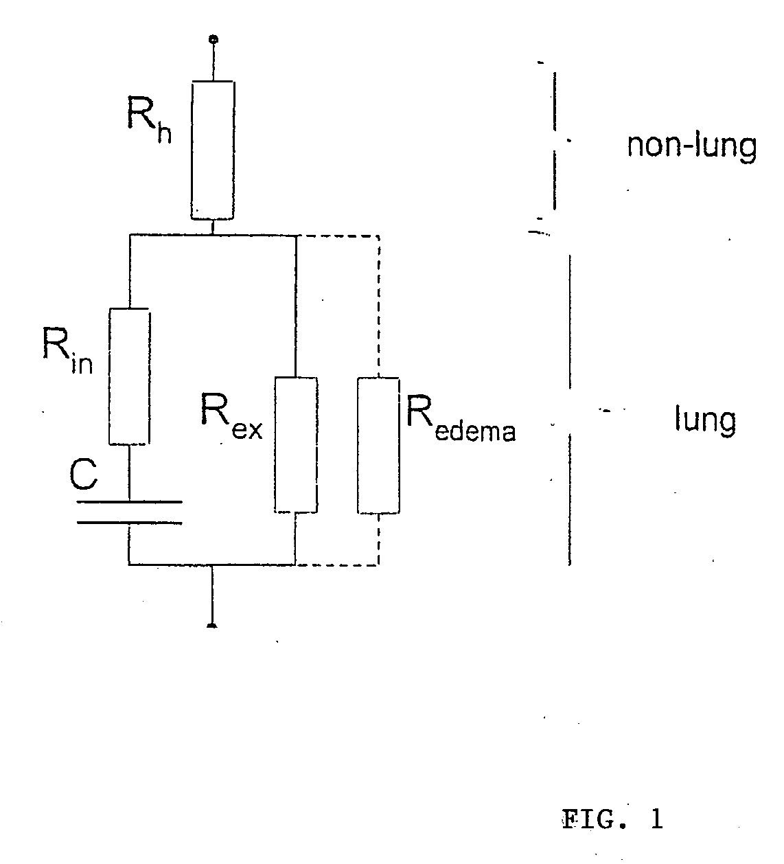
[0070]FIG. 1 shows a network of several discrete elements. This essentially results in a series connection of an ohmic resistance Rh, and in a parallel connection of several resistances and a capacitance C, where Rh denotes the resistance of the cardiac tissue in which a measuring electrode is arranged. For the sake of simplicity, other contact resistances of the two measuring electrodes are included in the resistance Rh. Parallel connection of the capacitance C and the ohmic resistances Rin, Rex and Roedema in approximation describes the resistance behaviour of the pulmonary tissue Rin, Rex and C which is situated between the heart and the electromedical implant. Rin, Rex and C characterize the electrical behavior of the healthy pulmonary tissue, while Roedema only occurs if the ohmic resistance of the pulmonary tissue is reduced due to oedema formation. In the substitute electrical replacement diagram, the ohmic resistance reduced by the oedema is taken into account by parallel co...


PUM


Abstract

An electromedical implant includes a measuring signal generator, an impedance measuring unit to determine the impedance of human or animal tissue, a control unit which, for controlling the measuring signal generator and the impedance measuring unit, is at least indirectly connected to the measuring signal generator and to the impedance measuring unit, as well as an electrode arrangement comprising at least two electrodes which can be directly or indirectly connected or at least temporarily connected to the measuring signal generator and to the impedance measuring unit, or to a connection for such an electrode arrangement. The measuring signal generator is designed to generate and emit a current pulse or a series of current pulses, and the control unit is designed at a specific point in time to cause the measuring signal generator (to generate and emit a current pulse, and to cause the impedance measuring unit to measure the voltage that is present between the electrodes connected to the measuring signal generator and the impedance measuring unit after the passing of at least two time periods of different length that start with commencement of the current pulse being emitted and end before the end of emitting the current pulse, and to issue a voltage value which in each case represents the measured voltage.

Description

BACKGROUND OF THE INVENTION [0001] The invention relates to an electromedical implant, such as for example, a cardiac pacemaker, cardioverter, defibrillator or a pure monitoring implant, which comprises means to detect the impedance of human or animal tissue. [0002] Furthermore, the invention relates to a system comprising at least one such electromedical implant which, in addition, comprises a wireless data interface, and to a patient device, a home monitoring service center or both. [0003] From the state of the art, electromedical implants with means to determine the impedance of human or animal tissue are for example known from U.S. Pat. No. 5,957,861. There, a device is presented which by regular measuring and long-term monitoring of the impedance of pulmonary tissue facilitates early detection of the formation of pulmonary oedema. Oedema are accumulations of fluid, which occur in particular in patients with chronic cardiac insufficiency. The body reacts to the heart's reduced p...

Claims


Application Information

Patent Timeline
Patent Type & Authority Applications(United States)
IPC IPC(8): A61N1/368
CPCA61B5/0537A61B5/0031
Inventor LIPPERT, MICHAELCZYGAN, GERALD
Owner BIOTRONIK SE & CO KG
Why Eureka
Try Eureka