Internal combustion engine with regenerator, hot air ignition, and naturally aspirated engine control
Inactive Publication Date: 2006-06-29
PATTON RICHARD
View PDF40 Cites 16 Cited by
Summary
Abstract
Description
Claims
Application Information
AI Technical Summary
This helps you quickly interpret patents by identifying the three key elements:
Problems solved by technology
Method used
Benefits of technology
[0061] The internal combustion engine of the present invention combines the fuel-saving features of a operating over a wide range of conditions within a narrow, efficient fuel ratio, low flame temperature, low heat losses, and high volumetric efficiency by using separate compression and power cy
Problems solved by technology
It is well recognized that the current generation of internal combustion (IC) engines lacks the efficiency needed to compete with fuel cells and other alternative vehicle movers.
The basic cause of the breakdown in the Carnot cycle rule is due to the fact that the properties of air change as the temperature increases.
This dissociation leads to increased exhaust pollution.
3) Power—Air is hot after firing, and begins to lose heat to the walls.
Luminosity of the diesel combustion process accounts for much of the heat lost.
Addition of water droplets, of course, is impossible with a Diesel engine.
The production of CO, carbon monoxide, is particularly undesirable, as it is a regulated pollutant.
All of these reactions also reduce the engine efficiency.
In the use of a regenerator, the state of the art is not yet commercially feas
Method used
Image
Click on the blue label to locate the original text in one second.
Reading with bidirectional positioning of images and text.
Examples
Embodiment Construction
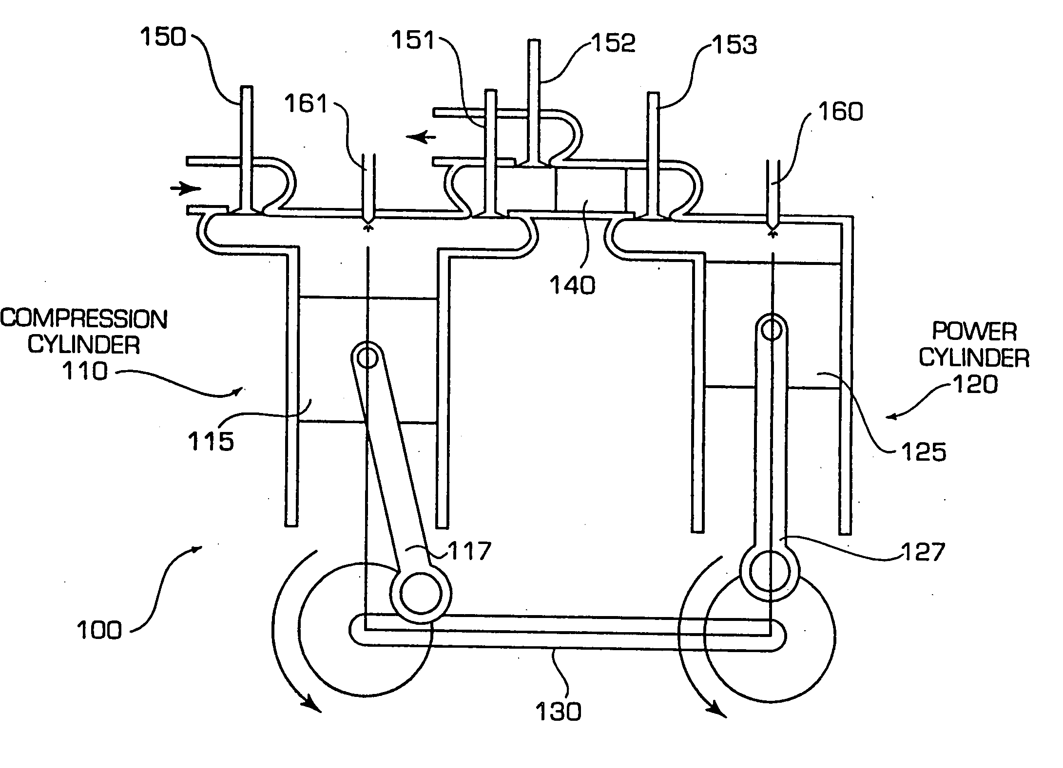
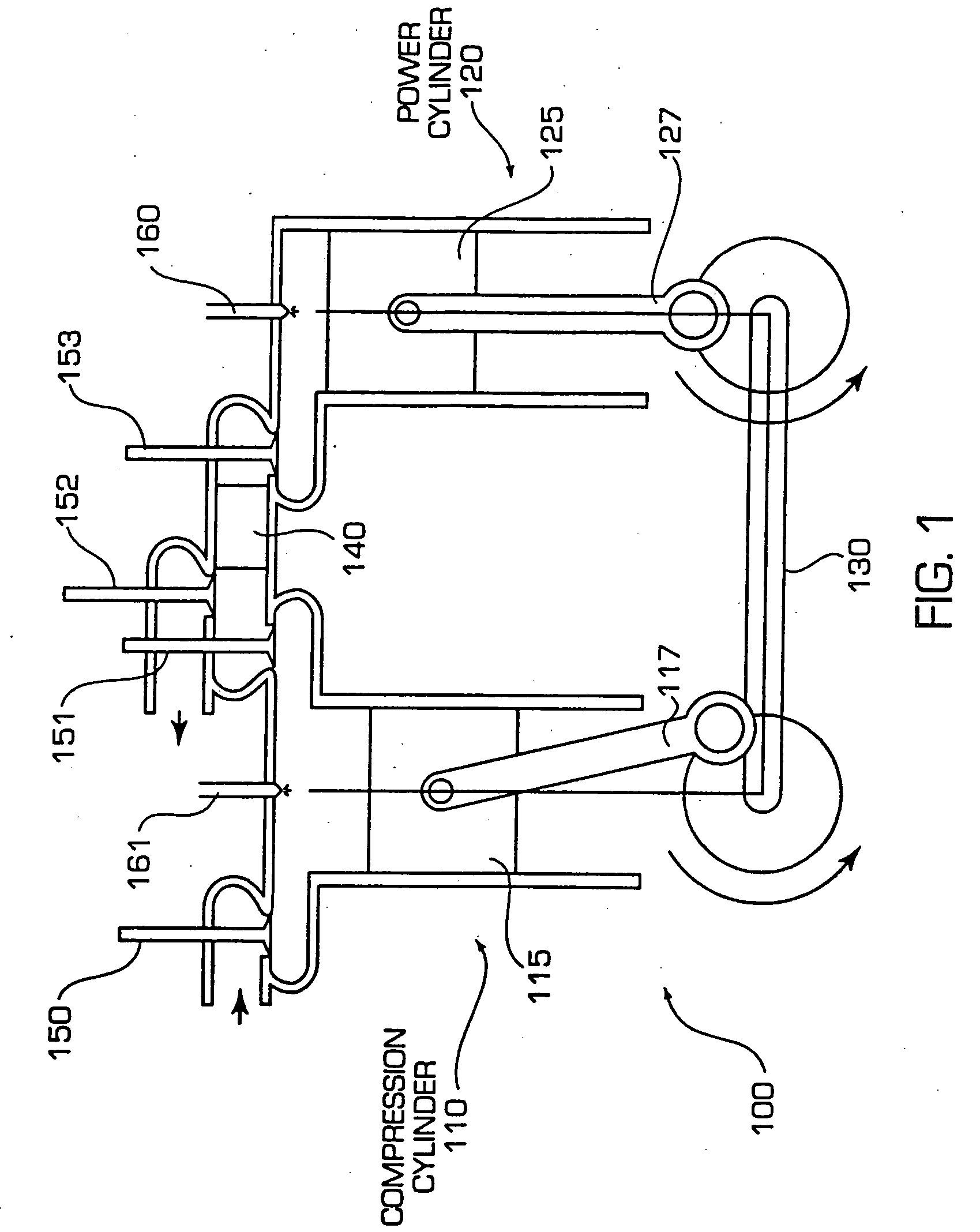
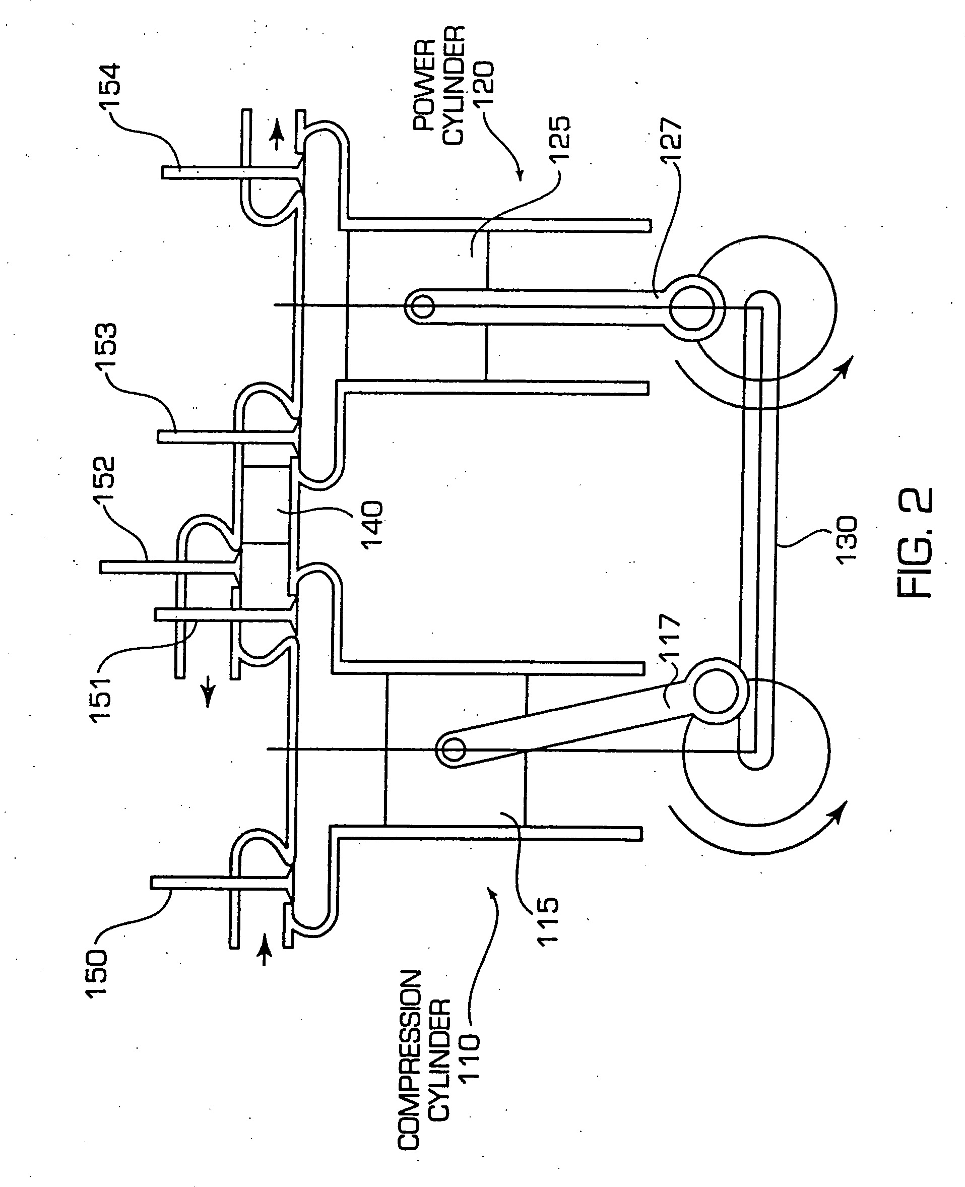
[0087] The engine of the present invention has separate cylinders for intake / compression (compression cylinder) and for power / exhaust (power cylinder). The compression cylinder is cool, and in fact during the intake and compression process, efforts can be made to create a nearly isothermal compression process by optionally adding water droplets to the intake air.
[0088] The power cylinder is the ‘hot’ cylinder, with typical head and piston temperatures in the range of 1000-1100 F. This necessitates the use of 18 / 8 (SAE 300 series) stainless steels for the head and piston, and superalloys for the valves. Combustion temperatures are in the neighborhood of 2000-3000 F. The high heat of the combustion chamber prior to combustion reduces the heat transfer from the working fluid to the chamber during the power stroke. It also reduces the radiant heat transfer, however the larger reduction in radiant heat transfer comes from keeping the maximum temperature below 3000 F.
[0089] The compress...
PUM
Abstract
An internal combustion engine and method is disclosed wherein separate compression and power cylinders are used and a regenerator or pair of regenerators is mounted between them to provide heat for hot-air ignition. The single regenerator embodiment operates as a two-stroke cycle engine and the embodiment with an alternating pair of regenerators operates as a four-stroke cycle engine. The engine varies the amount of air entering the power cylinder to control the engine output during naturally aspirated operation using valve timing and/or volume control of dead space and can optionally include supercharging to control the engine at higher output levels.
Description
RELATED APPLICATIONS [0001] This application is a continuation in part of application Ser. No. 10 / 638,208 filed Aug. 8, 2003, now pending and allowed, which is a continuation in part of application Ser. No. 09 / 978,151 filed Oct. 16, 2001, now U.S. Pat. No. 6,606,970, which is a continuation in part of application Ser. No. 09 / 651,482 filed Aug. 30, 2000, now U.S. Pat. No. 6,340,004, which claims the benefit of Provisional Application Ser. No. 60 / 151,994, filed Sep. 1, 1999, all of which are incorporated herein by reference.FIELD OF THE INVENTION [0002] This invention relates to the field of internal combustion engines, and in particular to the control of the regenerative engines disclosed in the present inventor's U.S. Pat. Nos. 6,340,004 and 6,606,970 when the engines are naturally aspirated. BACKGROUND OF THE INVENTION [0003] As discussed in U.S. Pat. No. 6,340,004, the fuel economy of vehicles primarily depends on the efficiency of the mover that drives the vehicle. It is well rec...
Claims
Application Information
Patent Timeline
Application Date:The date an application was filed.
Publication Date:The date a patent or application was officially published.
First Publication Date:The earliest publication date of a patent with the same application number.
Issue Date:Publication date of the patent grant document.
PCT Entry Date:The Entry date of PCT National Phase.
Estimated Expiry Date:The statutory expiry date of a patent right according to the Patent Law, and it is the longest term of protection that the patent right can achieve without the termination of the patent right due to other reasons(Term extension factor has been taken into account ).
Invalid Date:Actual expiry date is based on effective date or publication date of legal transaction data of invalid patent.