Light beam scanning display

Inactive Publication Date: 2006-06-29
FUJIFILM HLDG CORP +1
View PDF5 Cites 30 Cited by
  • Summary
  • Abstract
  • Description
  • Claims
  • Application Information

AI Technical Summary

Benefits of technology

[0024] According to this light beam scanning display, respective color laser beams can be led arbitrarily by the optical fibers

Problems solved by technology

Thus, an increase in size of the display is hardly avoidable.
Also, in the laser display set forth in U.S. Pat. No. 6,175,440, there are such disadvantages that, because a number of light sources are provided, a power required to drive respective lasers is increased and

Method used


Image

  • Light beam scanning display
  • Light beam scanning display
  • Light beam scanning display

Examples


first embodiment

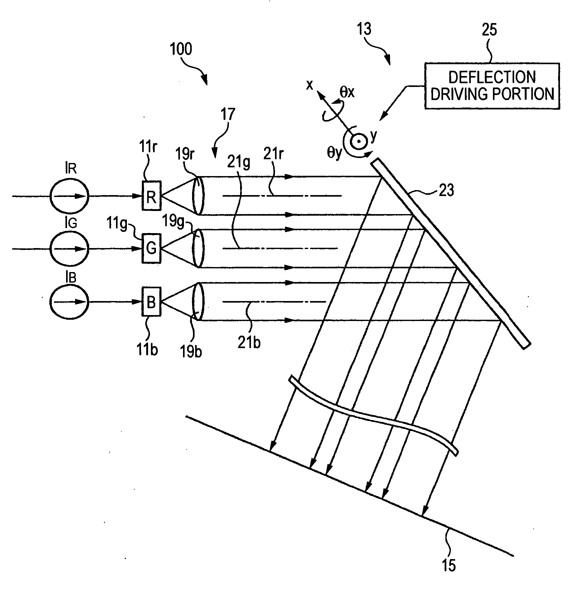
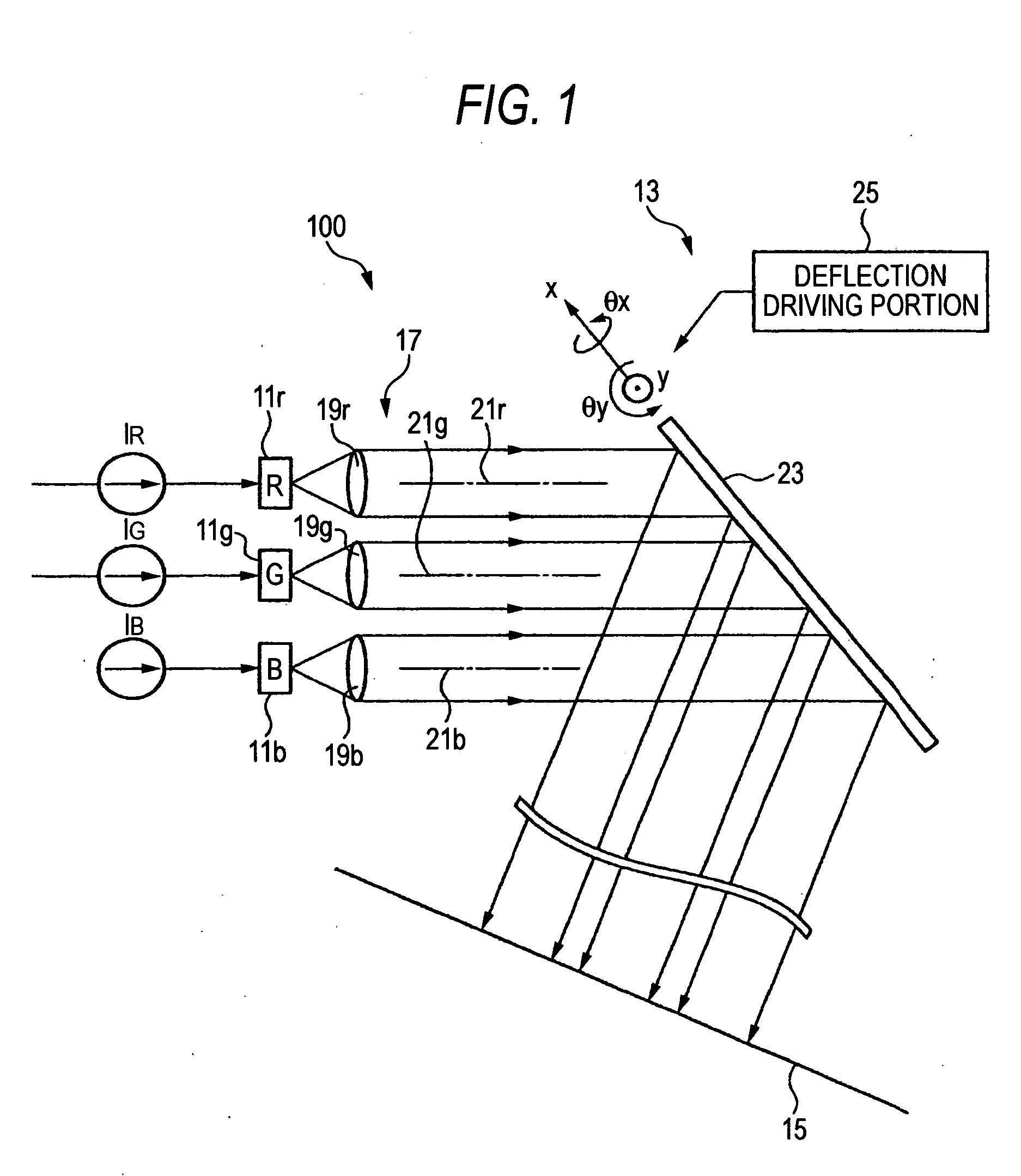
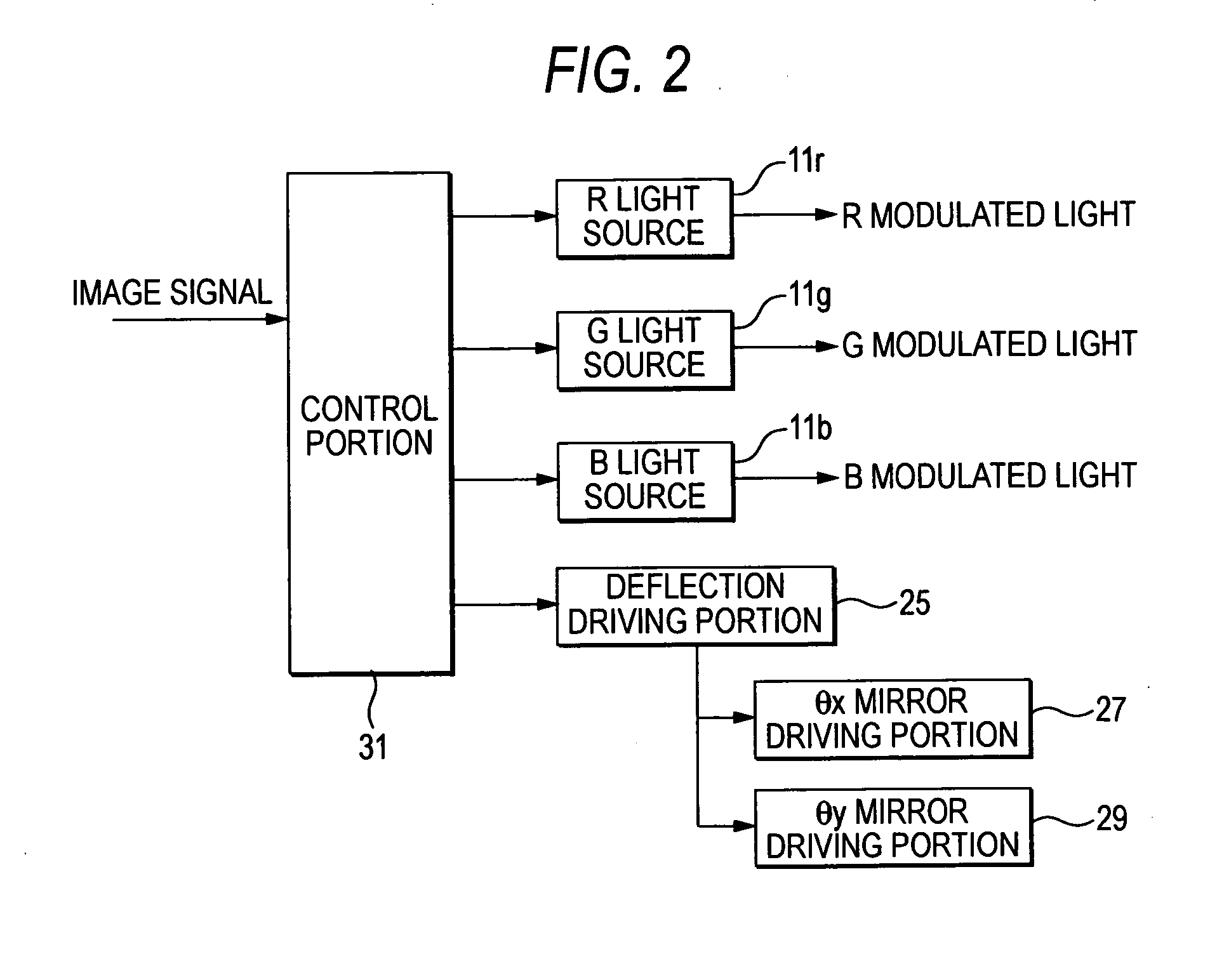
[0044]FIG. 1 is an overall-configurative view showing schematically a light beam scanning display, and FIG. 2 is a control block diagram of the light beam scanning display.

[0045] A light beam scanning display 100 displays an image on a drawing screen 15 by converting the laser beams emitted from three primary color laser light sources arranged in neighboring positions respectively, i.e., an R light source 11r, a G light source 11g, a B light source 11b, into parallel beams by lenses as a parallelizing section, modulating the laser beams based on input image data, and scanning these laser beams by a deflecting section 13.

[0046] As the R light source 11r, a semiconductor laser using an InGaP or InGaAlP quantum well formed on a GaAs substrate as an active layer can be employed.

[0047] As the G light source 11g, a semiconductor laser using InGaN formed on a GaN substrate as an active layer or a semiconductor laser using ZnCdSe formed on a ZnSe substrate as an active layer can be emplo...

second embodiment

[0073] Next, a second embodiment of the light beam scanning display, in which the RGB light sources are sealed in the package, according to the present invention will be explained hereunder.

[0074]FIG. 8 is a configurative view of a light source sealed in a package, wherein (a) is an external perspective view and (b) is an A-A sectional view, and (c) is a B-B sectional view.

[0075] In the present embodiment, as shown in FIG. 8(a), a light source 67 is a packaged parts that has terminals on the opposite side to the light emergent side and has the sealed light source. Also, as shown in FIG. 8(b), the light source 67 is constructed such that three primary color laser light sources, i.e., an R light source 69r, a G light source 69g, a B light source 69b, are arranged closely to each other on a flat surface 71a of a stem 71 and then the stem 71 is built in a cap 73.

[0076] Also, lenses 75r, 75g, 75b are arranged in the light source 67 to correspond to the laser beams emitted from the RGB...

third embodiment

[0080] Next, a third embodiment of the light beam scanning display according to the present invention, in which the RGB light sources are constructed as one package and also the lenses used to parallelize the laser beams are arranged on the outside of the package, will be explained hereunder.

[0081]FIG. 9 is a conceptual view showing an arrangement of the light sources and the lenses according to the present embodiment.

[0082] In the present embodiment, the R light source 69r, the G light source 69g, the B light source 69b of a light source 81 are arranged closely to each other on the stern 71, but lenses 83r, 83g, 83b used to parallelize the laser beams are arranged on the outside of the package of the light source 81.

[0083] The lenses 83r, 83g, 83b are provided to respond to the laser beams respectively. Also, the lens 83r is arranged to deviate its optical axis 87r from a beam center 85r of the R light source 69r by Δs. Also, the lens 83b is arranged to deviate its optical axis ...


PUM


Abstract

A light beam scanning display for displaying an image on a drawing screen by modulating laser beams from three primary color light sources, the three primary color light sources being arranged in close vicinity to each other, based on image data respectively and then scanning the laser beams, the light beam scanning display comprising: a parallelizing section that parallelizes respective laser beams; wherein the laser beams being parallelized by the parallelizing section to form one pixel of a drawn image on the drawing screen via different optical paths such that optical axes of the laser beams do not overlap with each other.

Description

BACKGROUND OF THE INVENTION [0001] 1. Field of the Invention [0002] The present invention relates to a light beam scanning display for displaying an image on a drawing screen by Using respective laser beams emitted from light sources in three primary colors. [0003] 2. Description of the Related Art [0004] The laser display using the laser light as the light source is disclosed in JP-A-2002-344765, for example. According to this laser display, the video information is visualized by propagating a plurality of modulated laser lights, which are emitted from the laser light sources in three colors of red (R), green (G) and blue (B) respectively, via the same path and then inputting the laser lights into the deflecting means to scan in the horizontal direction and the vertical direction. [0005] Also, as another laser display, the laser display for guiding the laser lights emitted from the RGE laser arrays as individual light source lights by using the optical fiber is set forth in JP-A-20...

Claims


Application Information

Patent Timeline
IPC IPC(8): G06K7/10
CPCG02B26/105G02B27/0961G02B27/30G03B21/2033H04N9/3129H04N9/3164G02B19/0057G02B19/0014
Inventor SONODA, SHINICHIROKIMURA, KOICHIMINATOGAWA, HIROSHI
Owner FUJIFILM HLDG CORP
Why Eureka
Try Eureka