
Method for manufacturing color element film-equipped substrate, color element film-equipped substrate, electro-optical device, and electronic device

Inactive Publication Date: 2006-06-29
SEIKO EPSON CORP
View PDF6 Cites 5 Cited by
  • Summary
  • Abstract
  • Description
  • Claims
  • Application Information

AI Technical Summary

Benefits of technology

[0008] It is an advantage of the invention to provide a method for manufacturing a color element film-equipped substrate, with which a high-quality color element film-equipped substrate can be obtained simply and at high production efficiency, as well as a color element film-equipped substrate, an electro-optical device, and an electronic device.
[0009] This advantage of the invention is realized as follows.
[0010] The method for manufacturing a color element film-equipped substrate of an aspect of the invention includes forming a bank, in which a first layer and a photo-curing second layer are laminated over a base, and parts of the first layer and the second layer are removed after exposing and developing the first layer and the second layer, with a remainder of the first layer and the second layer serving as a bank; applying a liquid material used for forming a color element film to a region demarcated by the bank; and forming a color element film by curing or solidifying the liquid material applied to the region. The first layer is soluble in a developing liquid during the developing, the second layer is soluble in the developing liquid but dissolves more slowly in the developing liquid than the first layer does, and the bank is formed with the width of the remainder of the second layer being greater than the width of the remainder of the first layer after the development.
[0011] Consequently, banks having a portion whose width steadily decreases toward the base can be easily formed without having to set the exposure conditions precisely in the bank formation step. More specifically, in the bank formation step, part of the second layer is put in a cured state by exposure, and part of the first layer and the uncured portion of the second layer are removed by developing. As a result, the portion in which the remainder of the second layer protrudes from the remainder of the first layer constitutes a protruding component of the color element film-equipped substrate of the inkjet (discussed below).
[0012] Also, in the application of liquid material, when the liquid material is applied to the regions demarcated by these banks, capillary action causes the liquid material to be drawn into every corner of the regions, even into the tiny gaps formed between the base and the portion where the remainder of the second layer protrudes beyond the remainder of the first layer (that is, the protruding component). As a result, a color element film-equipped substrate of higher quality can be obtained.
[0013] Also, since the width of the above-mentioned bank steadily decreases in stages toward the base, the surface area at the junction between the bank and the base can be comparatively increased. Accordingly, separation between the bank and the base can be prevented during developing in the bank formation step. As a result, a color element film-equipped substrate can be manufactured at higher production efficiency.

Problems solved by technology

However, with the color filter substrate pertaining to JP-A-2002-62422, in the formation of banks by photolithography, setting the exposure conditions is difficult because tapered banks have to be formed from a single photoresist layer.
Also, because this color filter substrate continuously tapers in the width of the banks toward the base, there is only a small surface area at the junction between the banks and the base, so the banks tend to separate from the base during the formation of the bank by photolithography, which is a problem in that the yield is diminished in the manufacture of a color filter substrate.

Method used


Image

  • Method for manufacturing color element film-equipped substrate, color element film-equipped substrate, electro-optical device, and electronic device
  • Method for manufacturing color element film-equipped substrate, color element film-equipped substrate, electro-optical device, and electronic device
  • Method for manufacturing color element film-equipped substrate, color element film-equipped substrate, electro-optical device, and electronic device

Examples


Embodiment Construction

[0051] The method for manufacturing a color element film-equipped substrate, the color element film-equipped substrate, the image display device, and the electronic device of the embodiments of the invention will now be described in detail through the specific embodiments shown in the appended drawings.

[0052] In these embodiments, a color filter substrate 10, which is a constituent element of a liquid crystal display device, will be described as a typical example of the color element film-equipped substrate of an embodiment of the invention.

[0053] Overall Structure of Droplet Discharge Apparatus

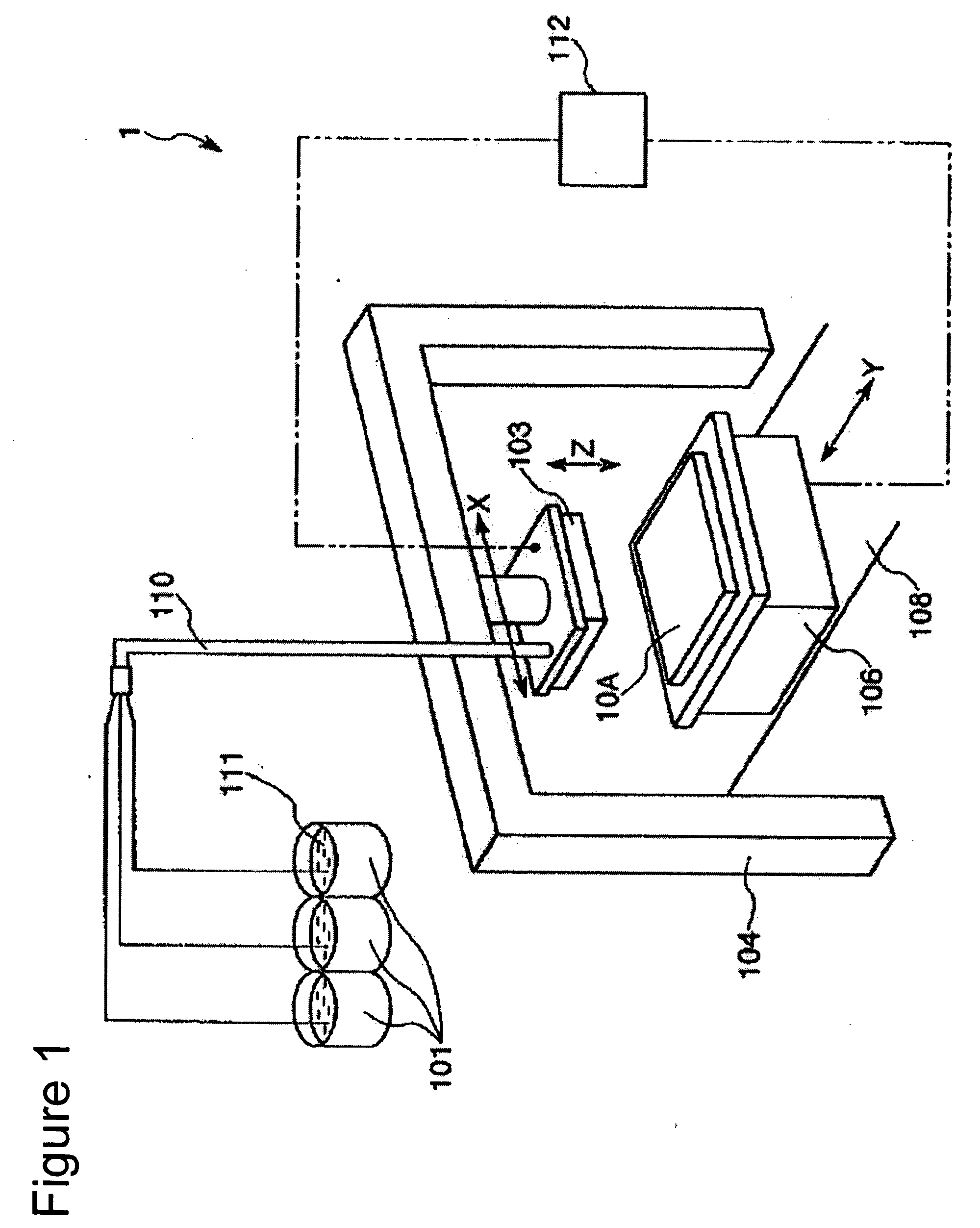
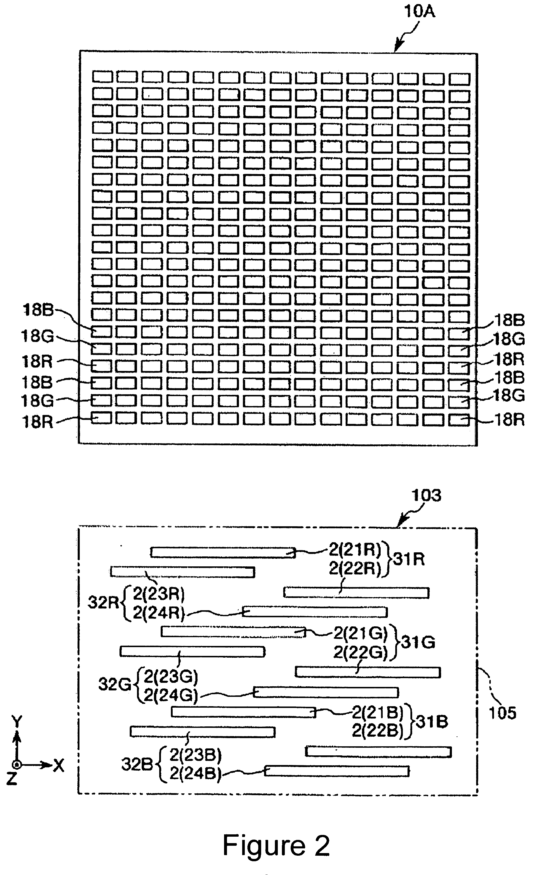
[0054] First, the droplet discharge apparatus used to manufacture the color element film-equipped substrate of the embodiment of the invention will be described through reference to FIGS. 1 to 6.

[0055] As shown in FIG. 1, a droplet discharge apparatus 1 includes a head unit 103 in which a plurality of droplet discharge heads 2 are mounted on a carriage 5, a carriage movement mechanism (mo...


PUM

PropertyMeasurementUnit
Widthaaaaaaaaaa
Heightaaaaaaaaaa

Abstract

A method for manufacturing a color element film-equipped substrate includes: forming a bank, in which a first layer and a photo-curing second layer are laminated over a base, and parts of the first layer and the second layer are removed after exposing and developing the first layer and the second layer, with a remainder of the first layer and the second layer serving as a bank; applying a liquid material used for forming a color element film to a region demarcated by the bank; and forming a color element film by curing or solidifying the liquid material applied to the region. The first layer is soluble in a developing liquid during the developing. The second layer is soluble in the developing liquid but dissolves more slowly than the first layer does. The bank is formed with the width of the remainder of the second layer being greater than the width of the remainder of the first layer after the development.

Description

BACKGROUND [0001] 1. Technical Field [0002] The present invention relates to a method for manufacturing a color element film-equipped substrate, to a color element film-equipped substrate, to an electro-optical device, and to an electronic device. [0003] 2. Related Art [0004] It is known that an inkjet apparatus can be used to apply ink or another such liquid material to regions demarcated by banks formed on a base, and to form a color element film by curing or solidifying this material. For example, there is a known method for using an inkjet apparatus to form light emitting components arranged in a matrix in a matrix-type display device, or filter elements in a color filter substrate (see JP-A-2002-62422, for example). [0005] For example, in JP-A-2002-62422, the banks that form the regions are formed so as to gradually and continuously taper in width toward the base, and the liquid repellency of the lower part of the banks with respect to the liquid material is lower than that of ...

Claims


Application Information

Patent Timeline
IPC IPC(8): B41M5/00H01L29/22H01L33/00B05C9/12B05D7/00G02B5/20G09F9/00H01L51/50H05B33/10
CPCB41M3/003B41M5/265Y10T428/24802H01L27/322G02F1/133516H10K59/38H05B33/10H05B33/22
Inventor KATAGAMI, SATORU
Owner SEIKO EPSON CORP
Learn More