Semiconductor device and adjusting method for semiconductor device

a technology of semiconductor devices and adjusting methods, which is applied in the direction of semiconductor/solid-state device details, line-transmission details, waveguide type devices, etc., can solve the problems of inability to prevent situations, inability to adjust center frequency cut by open stubs, and inability to stabilize the operation of semiconductor devices, so as to prevent noise propagation, reduce noise components, and prevent the effect of noise propagation

Inactive Publication Date: 2006-06-29
SOCIONEXT INC
View PDF2 Cites 11 Cited by
  • Summary
  • Abstract
  • Description
  • Claims
  • Application Information

AI Technical Summary

Benefits of technology

[0008] However, with the prior art described in the publication '522, a method for preventing noise propagation by reflecting a center frequency component of noise by a band filter 8 (open stub) is described, however, no description about a method for reducing noise components themselves is given. Therefore, reflected noise components exist as standing waves and may cause stable operations of the semiconductor device to be lost.

Problems solved by technology

Therefore, reflected noise components exist as standing waves and may cause stable operations of the semiconductor device to be lost.
Therefore, noise radiated as radio waves may influence the periphery including circuits, etc., inside the chip, and such a situation cannot be prevented.
Therefore, for each semiconductor device, the center frequency to be cut by the open stub cannot be adjusted according to a frequency including existence of a maximum value of noise that occurs in actuality.
Therefore, the semiconductor device is easily influenced by scattering of the center frequency of noise, so that the influence of power source noise cannot be effectively prevented.

Method used


Image

  • Semiconductor device and adjusting method for semiconductor device
  • Semiconductor device and adjusting method for semiconductor device
  • Semiconductor device and adjusting method for semiconductor device

Examples


first embodiment

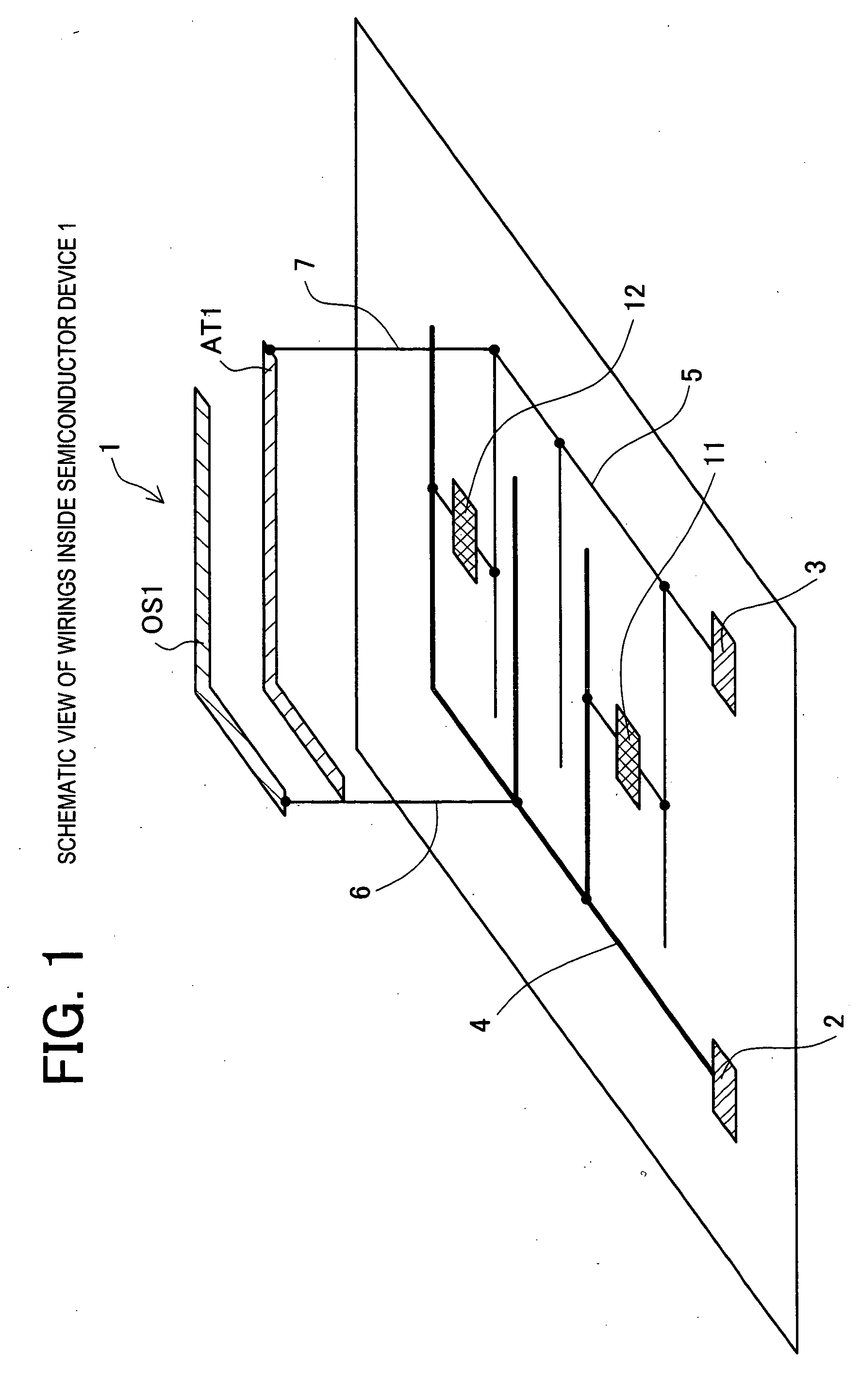
[0042] According to the semiconductor device 1 of the first embodiment, as described in detail above, propagation of power source noises in the power source wiring between blocks inside the semiconductor device can be prevented by the open stub. Therefore, not only erroneous operations due to noise propagation between semiconductor devices but also erroneous operations due to noise propagation between block circuits inside the semiconductor device can be prevented. Therefore, noise cutting can be carried out pinpoint in smaller units, that is, at a level of noise cutting between blocks, and this more effectively prevents noises from propagating and prevents the semiconductor device from erroneously operating.

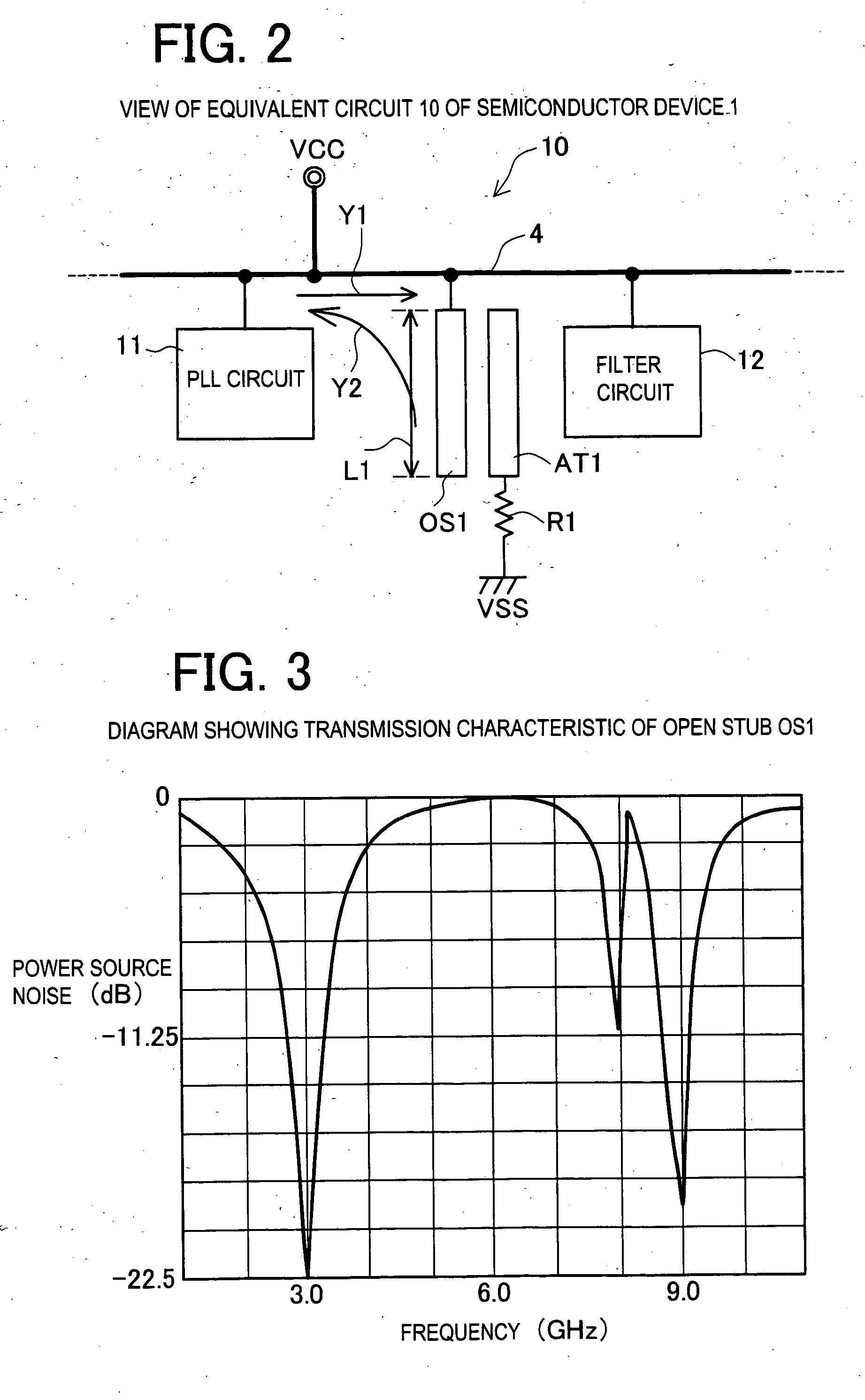
[0043] Furthermore, by providing the noise receiving part including resistor components, not only are the frequency components of noises reflected but also the noise components themselves are reduced by impedance. Namely, in comparison with the case where no noise receiving part...

second embodiment

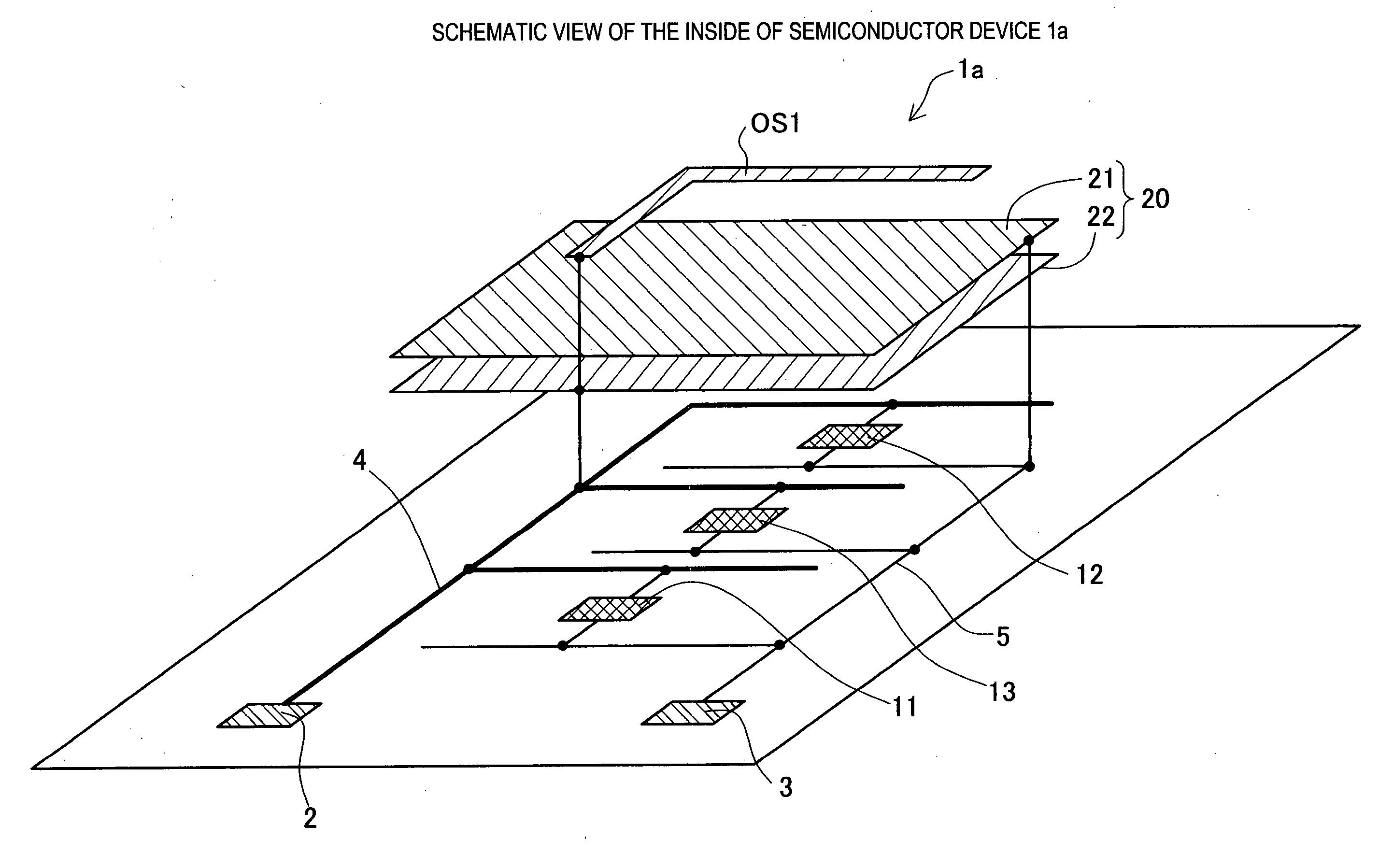
[0044] the invention is described with reference to FIG. 4. The second embodiment is an embodiment in which a shield is provided inside the chip in the case where the open stub to be connected to the power source wiring is disposed inside the chip of the semiconductor device. A schematic view of the inside of a semiconductor device 1a relating to this embodiment is shown in FIG. 4. The semiconductor device 1a has a shield part 21 and a power source electrode part 22 in place of the noise receiving part AT1 described in the first embodiment. The shield part 21 has a wide area to cover the open stub OS1 so as to shield it from radio waves radiated from the open stub OS1. By forming the shield part 21 in the wiring layer just below the wiring layer including the open stub OS1 by the method for forming metal wiring, the shield part 21 is disposed adjacent to the open stub OS1. Furthermore, by forming the power source electrode part 22 in the wiring layer just below the wiring layer incl...

third embodiment

[0053] As described in detail above, according to the semiconductor device of the third embodiment, by disposing the open stub between the power source wiring of the input and output terminals of the semiconductor device and the external device, the basic wave component and odd-number harmonic components of noises can be prevented from leaking from the semiconductor device to the outside. Therefore, an apparatus itself that includes the semiconductor device can be prevented from erroneously operating. Furthermore, by forming the open stub so as to have a plurality of bends, it becomes possible that the maximum side length of a region required for installing the open stub can be reduced while maintaining the length corresponding to the ¼ wavelength at the predetermined center frequency of power source noises. Therefore, the degree of freedom in the form of the open stub installation location is increased, so that the situation in that the installation location cannot be obtained and ...


PUM


Abstract

An object of the invention is to provide a semiconductor device and an adjusting method for a semiconductor device wherein power source noises and noises radiated as radio waves can be reduced and power source noises inside the semiconductor device can be cut. The open stub OS1 is formed in the upper wiring layer of the semiconductor device 1. The stub length L1 is set to a length of ¼ of the wavelength of the known frequency containing peak components of noises. The noise receiving part AT1 is disposed adjacent to the open stub OS1. The open stub OS1 is connected to the power source wiring 4 by an interlayer wiring 6. The noise receiving part AT1 is biased to a ground potential. The basic wave component and odd-number harmonic waves of noises that are generated from the PLL circuit 11 and propagate (the arrow Y1 of FIG. 2) in the power source wiring 4 are reflected (arrow Y2 of FIG. 2) by the open stub OS1 so as to return to the PLL circuit 11, and do not reach the filter circuit 12.

Description

CROSS-REFERENCE TO RELATED APPLICATIONS [0001] This application is based upon and claims the benefit of priority from each of the prior Japanese Patent Application No. 2004-374482 filed on Dec. 24, 2004, the entire contents of which are incorporated herein by reference. BACKGROUND OF THE INVENTION [0002] 1. Field of the Invention [0003] The present invention relates to power source noise control of a semiconductor device, and more specifically, noise control using an open stub. [0004] 2. Description of Related Art [0005] In recent semiconductor integrated circuits, higher integration and higher synchronization speeds are realized, and clock skew is reduced for realizing high-speed stable operations. Therefore, timings of through currents are synchronized, and power source noise tends to increase. Furthermore, according to the increase in speed of a multi-pin integrated circuit, switching of an output buffer or the like causes synchronous switching noise which fluctuates the power so...

Claims


Application Information

Patent Timeline
Patent Type & Authority Applications(United States)
IPC IPC(8): H01P1/00
CPCH01L23/66H01L2223/6677H01L2924/3011H01P1/203H01L2924/0002H01L2924/00
Inventor ASANO, SHIGETAKA
Owner SOCIONEXT INC
Why Eureka
Try Eureka