Mold for forming spacers for flat panel displays

a technology for forming spacers and flat panels, which is applied in the direction of photomechanical equipment, instruments, transportation and packaging, etc., can solve the problems of reducing the quality of the fed, reducing the adhesion strength, and not allowing the precise alignment of the spacers with respect to the pixel array, so as to achieve superior properties and increase the adhesion strength

Inactive Publication Date: 2006-06-29
HOFMANN JAMES J +3
View PDF17 Cites 3 Cited by
  • Summary
  • Abstract
  • Description
  • Claims
  • Application Information

AI Technical Summary

Benefits of technology

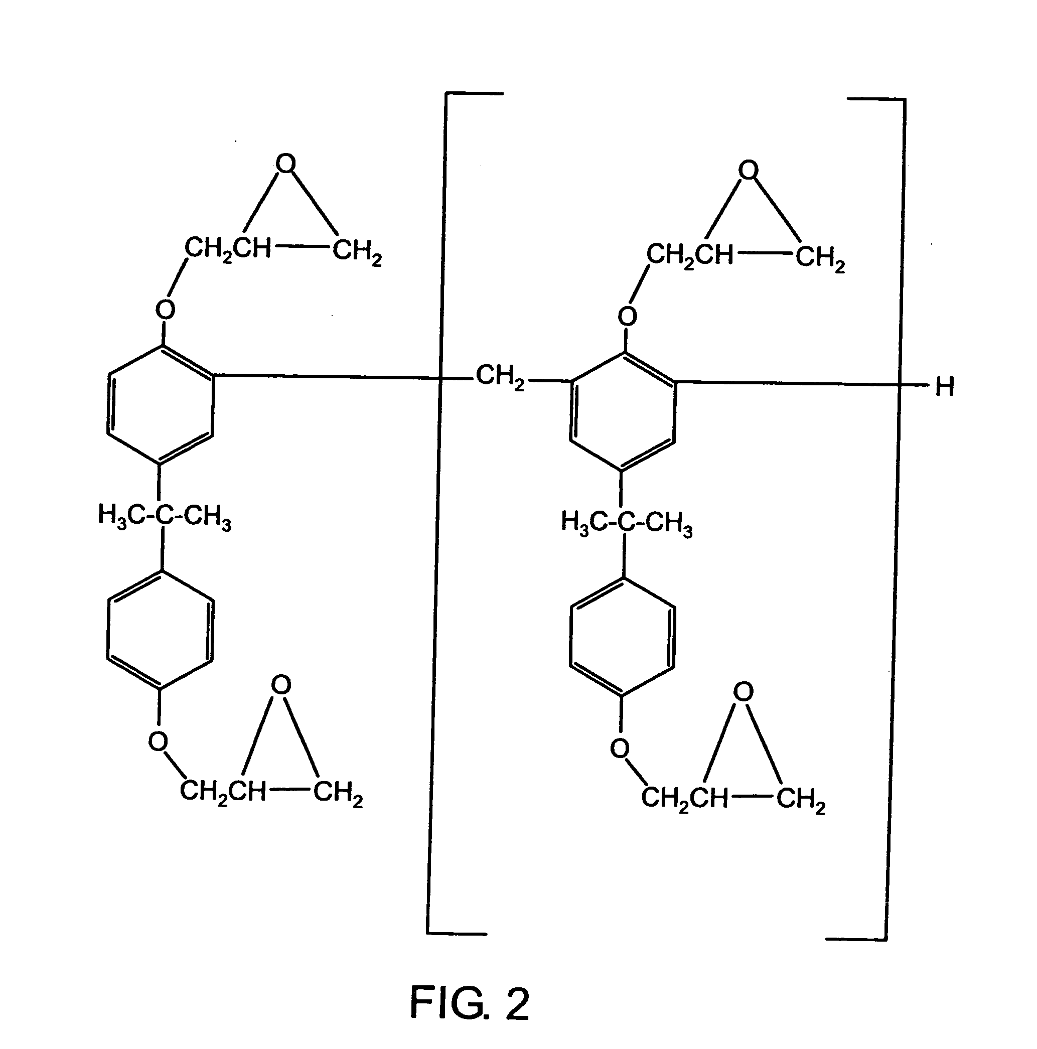
[0015] One preferred thick film photoresist for use in fabricating the molds comprises an epoxy bisphenol A novolac resin, such as EPON® Resin SU-8. Methods are disclosed below for depositing a thick film of an epoxy bisphenol A novolac resin onto a support (e.g., a glass panel), for patterning the epoxy bisphenol A novolac resin layer into a desired shape for a mold, for improving the ability of the epoxy bisphenol A novolac resin to adhere to the support, for making the cured epoxy bisphenol A novolac resin less brittle or more resilient, and for planarizing a thick layer of uncured epoxy bisphenol A novolac resin.

Problems solved by technology

For example, when the spacers are fabricated from glass posts, it is difficult to ensure that every spacer has precisely the same height.
Variation in spacer height degrades the parallel alignment between the faceplate and baseplate and thereby degrades the quality of the FED.
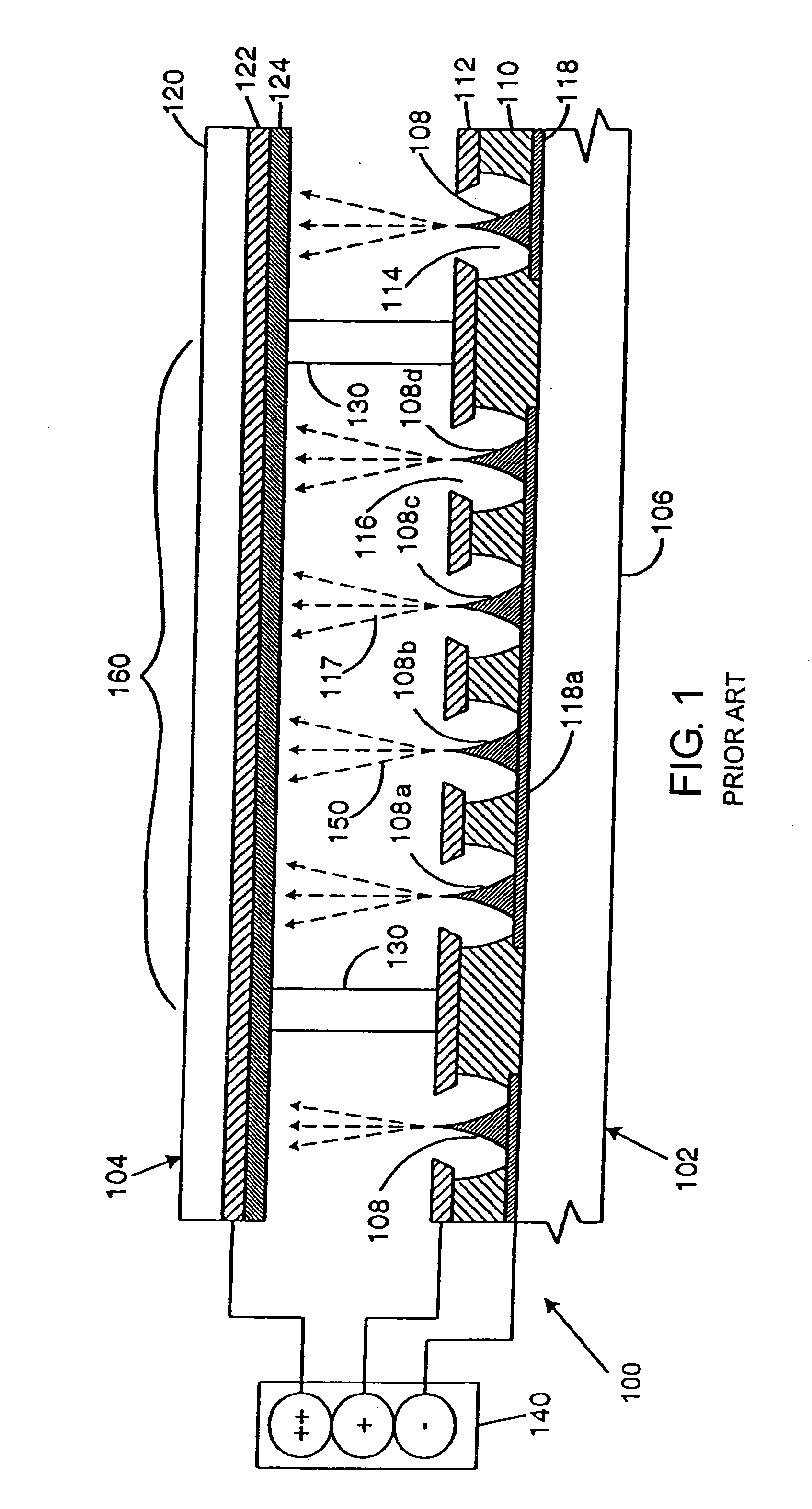
Another problem with prior art spacer manufacturing techniques is that they do not permit precise alignment of the spacers with respect to the pixel array.
As stated above, any deviation from the desired alignment can cause the dark regions created where the spacers contact the faceplate 104 to degrade the quality of the display.
Ideally, the bottom of each spacer 130 contacts the grid layer 112 at a point that is equidistant from all the adjacent emitters, however, prior art spacer manufacturing techniques make it difficult to achieve this ideal.
There are several problems associated with this process.
These methods prevent the posts from being accurately positioned.
Second, the posts formed by the techniques disclosed therein tend to be contaminated by air bubbles.
That is, air bubbles tend to form near the base of the posts thereby weakening the posts as well as weakening the attachment between the posts and the substrate.

Method used


Image

  • Mold for forming spacers for flat panel displays
  • Mold for forming spacers for flat panel displays
  • Mold for forming spacers for flat panel displays

Examples


example 1

Glass-Resist Adhesion

[0130] A mold fabricated from SU-8 can be formed as described herein. Briefly, a support, such as soda lime glass, is cleaned and coated with a thin film of SU-8 resist (e.g., about 50 μm), which is then flood-exposed to completely cure the SU-8 resist. A thicker film of the SU-8 resist is then applied (e.g., 200 to 600 μm), exposed with the desired photopattern, baked, and developed in a PGMEA solvent. Negative resist allows the process of coating, exposing and developing to be repeated, such that a complex 3D shape can be formed.

[0131] As described herein, adhesion of the SU-8 resist to a glass support can be poor, such that delamination occurs when the SU-8 resist exceeds a thickness of 200 μm. A search for possible priming methods was carried out in three broad categories: (1) cleaning processes that leave the surface hydrophilic; (2) cleaning processes that leave the surface hydrophobic; and (3) depositing several monolayers of molecules to promote adhesi...

example 2

Modification of SU-8

[0135] Propanediol and hexanediol were added to an SU-8 resist to determine the effects on the properties of the SU-8. As shown in FIGS. 13A-B, the photospeed of the propanediol / SU-8 mix and the hexanediol / SU-8 mix was faster than the photospeed of the SU-8 alone, and the adhesive strength of the propanediol / SU-8 mix with the support and the hexanediol / SU-8 mix with the support was better than the adhesive strength of the SU-8 alone.

example 3

Sol Gel Post-Mold Treatment

[0136] After the sol gel spacers are formed, they must be washed and dried, as described herein.

[0137] Washing the wet gels in deionized water can lead to swelling and cracking if care is not taken to balance the osmotic pressure between the solvent and the gel network. Sol gels will match the dilution of the ionic species it is immersed in by swelling or shrinking. Since the sol gels of the present invention contain a large amount of sodium and potassium, they will swell and rupture when placed in deionized water. When the sol gels of the present invention are washed in a solution of deionized water saturated with NaCl, they tend to shrink and expel water because the ion concentration gradient is higher outside the gel than inside. Thus, it has been found that a 1 to 10% solution of HCl in deionized water can effectively wash the sol gels of the present invention without swelling.

[0138] After washing, the gels must be dried. An increasing temperature c...


PUM

PropertyMeasurementUnit
aspect ratioaaaaaaaaaa
thickaaaaaaaaaa
thickaaaaaaaaaa

Abstract

The present invention describes thick film photolithographic molds, methods of making thick film photolithographic molds, and methods of using thick film photolithographic molds to form spacers on a substrate. The thick film photolithographic molds preferably comprise an epoxy bisphenol A novolac resin. The present invention also describes sol gel spacers comprising sodium silicates and potassium silicates. The thick film photolithographic molds and sol gel spacers of the present invention can be used in flat panel displays, such as field emission displays and plasma displays.

Description

CROSS-REFERENCE TO RELATED APPLICATIONS [0001] This application is a divisional of application Ser. No. 10 / 978,323, filed Nov. 1, 2004, pending, which is a divisional of application Ser. No. 09 / 560,260, filed Apr. 26, 2000, now U.S. Pat. No. 6,812,990, issued Nov. 2, 2004.STATEMENT REGARDING FEDERALLY SPONSORED RESEARCH OR DEVELOPMENT [0002] The present invention was made with Government support under Contract No. DABT63-97-C-0001 awarded by the Advanced Research Projects Agency (ARPA). The Government may have certain rights in this invention.FIELD OF THE INVENTION [0003] The present invention describes thick film photolithographic molds, methods of making thick film photolithographic molds, and methods of using thick film photolithographic molds to form spacers on a substrate. The thick film photolithographic molds preferably comprise an epoxy bisphenol A novolac resin. The present invention also describes sol gel spacers comprising sodium silicates and potassium silicates. The thi...

Claims


Application Information

Patent Timeline
Patent Type & Authority Applications(United States)
IPC IPC(8): G02F1/1339B05D5/12B29C33/38B29C59/00
CPCB29C33/3857G02F1/1339Y10T428/1059G03F7/0017H01J2211/36G02F1/13394C09K2323/05
Inventor HOFMANN, JAMES J.VAARTSTRA, BRIAN A.KRAUS, BRENDA D.WESTMORELAND, DONALD L.
Owner HOFMANN JAMES J
Why Eureka
Try Eureka