

Surface reflection type phase grating
a technology of surface reflection and phase grating, which is applied in the direction of instruments, optical elements, optics, etc., can solve the problems of inability to achieve high-quality displacement measurement, etc., and achieves high-quality and easy-to-manufacture effects
- Summary
- Abstract
- Description
- Claims
- Application Information
AI Technical Summary
Benefits of technology
Problems solved by technology
Method used
Image

Examples
embodiment 1
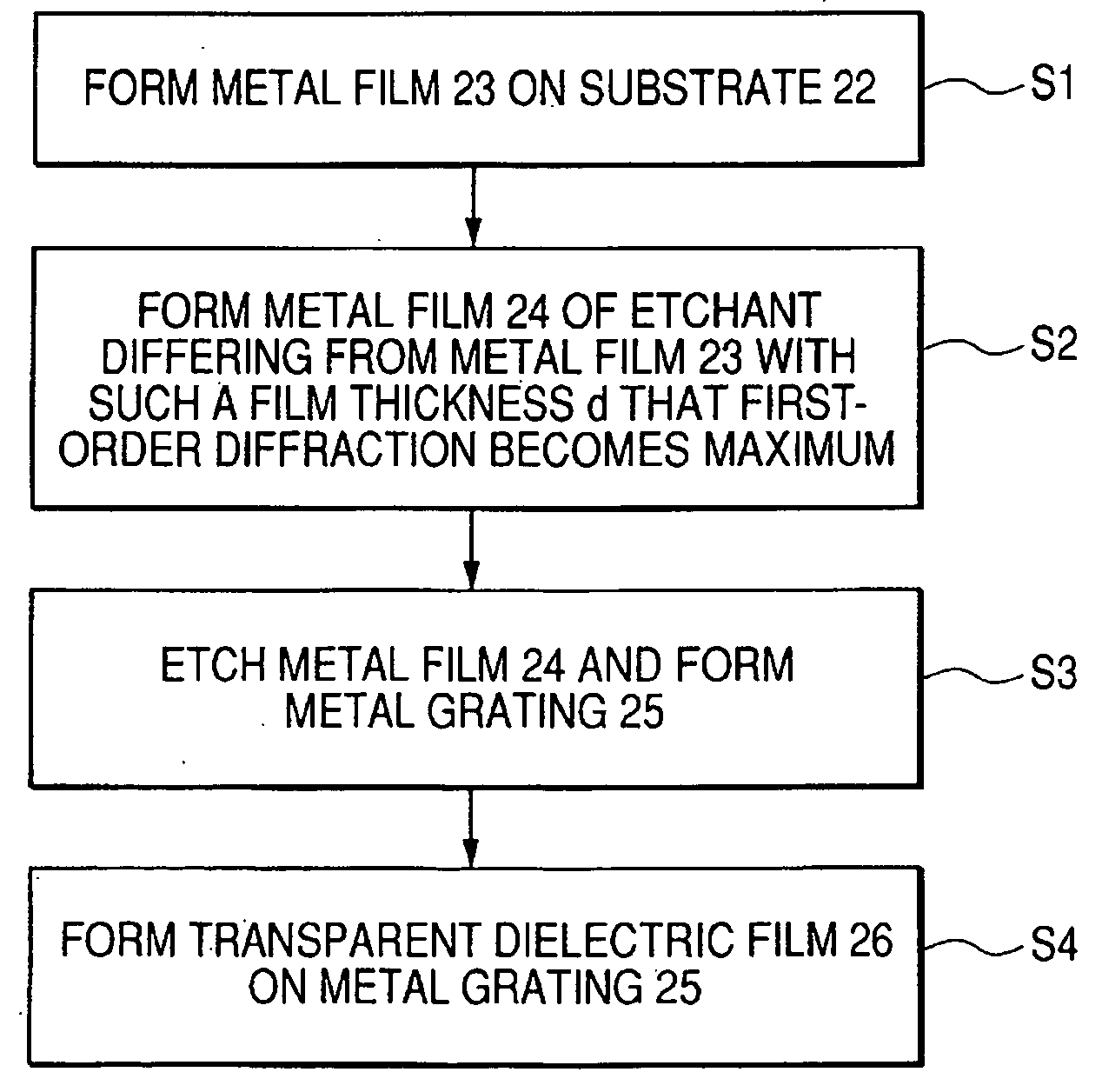
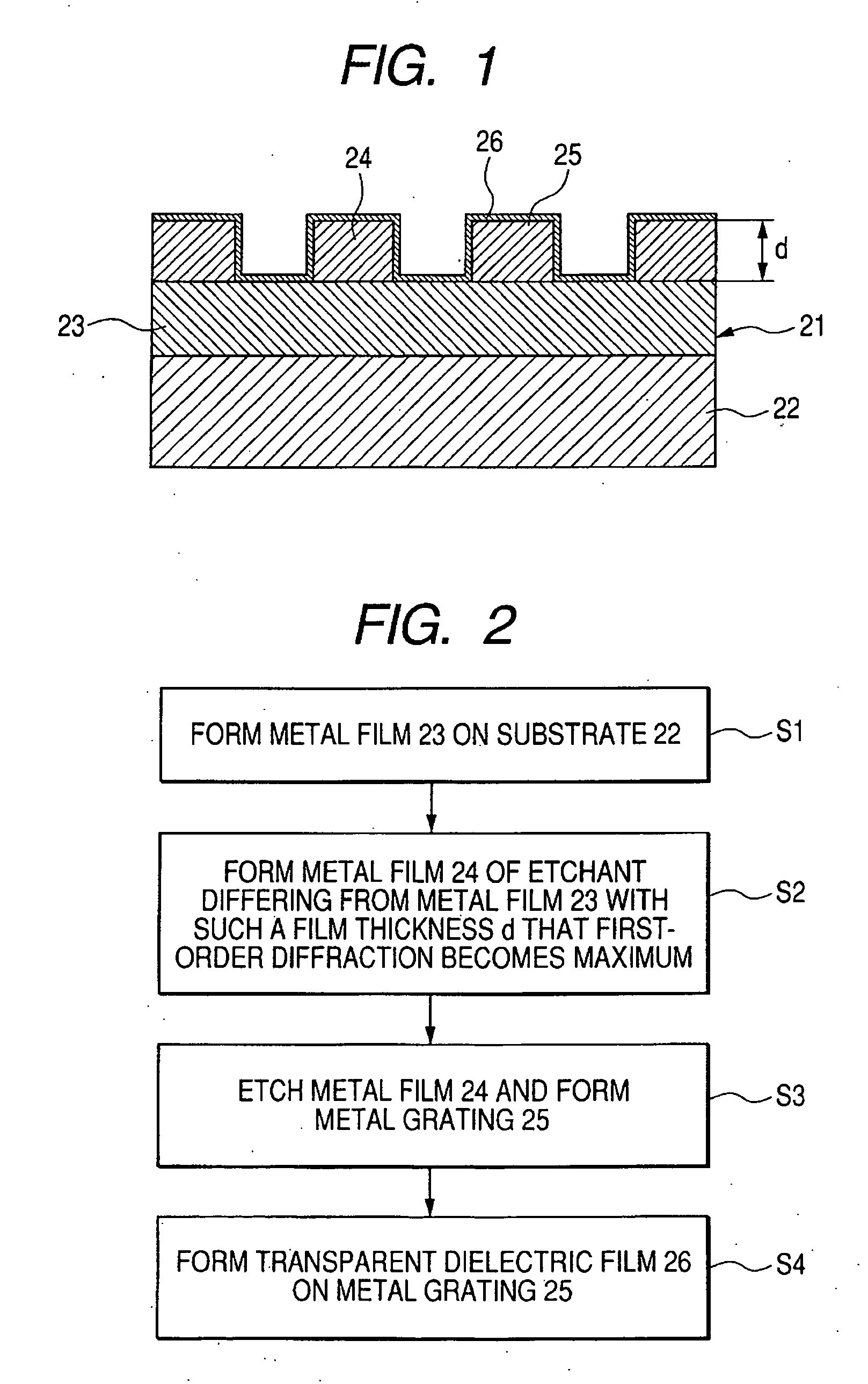
[0040]FIG. 1 is a cross-sectional view of a surface reflection type phase grating 21 having a relief type diffraction grating having a rectangular cross-sectional shape.
[0041] First metal film 23 is formed on a substrate 22.
[0042] On the first metal film 23, there are formed metal gratings 24 of a rectangular cross-sectional shape having a thickness d by second metal film formed of a material differing from that of the first metal film 23.
[0043] The thickness d of the metal gratings 24 is set so that first-order diffraction may become maximum.
[0044] Here, when n is the refractive index of the substrate, and λ is the wavelength of a light source used, the thickness d of the diffraction grating for which the first-order diffraction becomes maximum is d=nλ / 4.
[0045] Further, on the surfaces of the metal gratings 24 and the first metal film 23 exposed among them, there is formed transparent dielectric film 26 formed of e.g. SiO2 by CVD method.
[0046] As described above, the transpar...
embodiment 2
[0057] As in Embodiment 1, transparent dielectric film 26 comprising SiO2 film is formed, whereafter as shown in FIG. 5, MgF2 film 27 is further formed on the transparent dielectric film 26. The film thickness of this MgF2 film 27 is designed such that transmittance becomes maximum.
[0058] In the case of this surface reflection type phase grating 21, light passes through the MgF2 film 27 and the transparent dielectric film 26 formed of SiO2, whereby a reflection preventing effect occurs, and the loss of the light can be suppressed. Accordingly, when diffracted lights produced by the surface reflection type phase grating 21 are made to interfere with each other, and any change in the light and darkness of the interference light is detected to thereby measure the amount of displacement of the object to be inspected, a stable output signal is obtained from a light receiving element, and still more highly accurate measurement becomes possible.
embodiment 3
[0059]FIG. 6 shows a cross-sectional view of a surface reflection type phase grating 31 according to Embodiment 3. In FIG. 6, the same members as those in Embodiment 1 are given the same reference characters.
[0060] In Embodiment 3, transparent dielectric film 32 formed of SiO2 is embedded among metal gratings 24 and in the surfaces of the metal gratings 24.
[0061] Further, the surface of the embedded transparent dielectric film 32 is smoothed by CMP or the like, whereby the metal gratings 24 are not exposed to the atmosphere and accordingly, the strength of the metal gratings 24 is improved.
[0062] Again by adopting Embodiment 3, highly accurate measurement becomes possible as in the aforedescribed embodiments.
[0063] Again in Embodiment 3, as in Embodiment 2, MgF2 film of a film thickness for which transmittance becomes thickness for which transmittance becomes maximum can be formed on the smoothed transparent dielectric film 32. By such a construction, a reflection preventing eff...
PUM
| Property | Measurement | Unit |
|---|---|---|
| reflection | aaaaa | aaaaa |
| depth | aaaaa | aaaaa |
| refractive index | aaaaa | aaaaa |
Abstract
Description
Claims
Application Information