
Sealant drawing method, sealant drawing apparatus, and method and apparatus for manufacturing liquid crystal device

Inactive Publication Date: 2006-06-29
138 EAST LCD ADVANCEMENTS LTD
View PDF5 Cites 3 Cited by
  • Summary
  • Abstract
  • Description
  • Claims
  • Application Information

AI Technical Summary

Benefits of technology

[0008] An advantage of some aspects of the invention is that it provides a sealant drawing method and a sealant drawing apparatus, in which drawing can be efficiently performed with a simplified control system. Another advantage of some aspects of the invention is that it provides a method and apparatus for manufacturing high-quality liquid crystal devices, which can realize a uniform cell gap even when sealant having a high viscosity is used, at low cost.
[0015] In the invention, however, the first patterns and the second patterns can be drawn and formed in a continuous way and in a batch manner in the direction in which the plurality of panel formation regions is arranged. Therefore, drawing can be started and ended for every column or row of each of the plurality of panel formation regions, and the drawing start number and the drawing end number can be reduced accordingly. This makes it possible to continuously draw the first patterns and the second patterns in a batch manner while the sealing material within the coating unit is made to flow stably. It is also possible to draw sealant in a short period of time. In addition, in a single process from the drawing start to the drawing end of the first patterns and a single process from the drawing start to the drawing end of the second patterns, the coating unit does not scan the plurality of panel formation regions in a non-discharge state, whereby the sealing material filled into the coating unit can be prevented from inadvertently dropping. Therefore, the operation of the coating unit can be simplified and the coating unit can also be easily controlled. It is thus possible to prohibit variation in the viscosity or in a discharge amount of the sealing material. In addition, since it is not necessary to take into consideration of the variation in viscosity between lots of the sealing material, the shape of the sealing materials can be easily managed. Furthermore, since the sealant can be drawn easily and quickly, a drawing method with improved productivity can be realized.
[0017] In this case, there is a tendency that bead-shaped drawing pools are likely to generate at the drawing start position due to a larger amount of sealant being discharged from the nozzle as compared with a discharge state. Furthermore, in the case where the formation of the first patterns and the formation of the second patterns are performed in the same direction, drawing pools at drawing start positions become noticeable profound because the drawing start positions are the same. Therefore, the thickness of the sealant on the panel formation region increases.
[0030] Therefore, the sealant can be continuously drawn in a batch manner in a direction, in which the plurality of panel formation regions is arranged, by a single process from the drawing start to the drawing end of a first pattern and a single process from the drawing start to the drawing end of a second pattern. Further, drawing can be started and ended for every column or row of the plurality of panel formation regions, and the drawing start number and the drawing end number can be reduced accordingly. This makes it possible to continuously draw the first pattern and the second pattern, while the sealant stably flows within the coating unit. It is also possible to draw the sealant in a short period of time. In addition, in a single process from the drawing start to the drawing end of a first pattern and a single process from the drawing start to the drawing end of a second pattern, the coating unit does not scan a plurality of panel formation regions in a non-discharge state. It is thus possible to prevent the sealing material filled into the coating unit from inadvertently dropping. Therefore, the operation of the coating unit can be simplified and the coating unit can also be easily controlled. It is thus possible to prohibit variation in the viscosity or in the discharge amount of the sealing material. In addition, since it is unnecessary to take into consideration of variation in viscosity between lots of the sealing material, the shape of the sealing material can be easily managed. Since the sealant can be drawn easily and quickly, a drawing method with improved productivity can be realized.
[0032] Through this construction, a plurality of first patterns or a plurality of second patterns can be drawn at the same time. This makes it possible to improve the productivity as compared with a case where only one coating unit is used.
[0035] Through this apparatus, the same effects as those of the sealant drawing method can be obtained. In addition, in the case where a sealant is formed in each of a plurality of panel formation regions as in the related art, the drawing start and the drawing end of the sealant must be performed on each region. In the invention, however, sealants can be continuously drawn on a plurality of panel formation regions in a batch manner. Therefore, liquid crystal devices can be fabricated at low cost through the improvement of the productivity. Liquid crystal devices, which are void of the defective cell gap, having a high quality display can be fabricated.

Problems solved by technology

However, the screen-printing method is problematic in that nonconformity sometimes occurs since the screen is brought in contact with the inner surface of the substrate.
Furthermore, in a method of pushing out sealant by means of air pressure, it is difficult to uniformly discharge sealant having a high viscosity.
In the case of manufacturing a liquid crystal device by drawing sealant having a high viscosity, as in JP-A-2004-290885, however, if the drawing start position and the drawing end position of the sealant overlap each other, a defective cell gap is likely to occur due to the thickness of the sealant.
Therefore, it is difficult to draw the sealant in a short period of time.

Method used


Image

  • Sealant drawing method, sealant drawing apparatus, and method and apparatus for manufacturing liquid crystal device
  • Sealant drawing method, sealant drawing apparatus, and method and apparatus for manufacturing liquid crystal device
  • Sealant drawing method, sealant drawing apparatus, and method and apparatus for manufacturing liquid crystal device

Examples


Embodiment Construction

[0051] Hereinafter, a sealant drawing method, a sealant drawing apparatus, and a method and apparatus for manufacturing liquid crystal devices according to the invention will be described in detail in connection to embodiments with reference to the accompanying drawings.

Sealant Drawing Apparatus

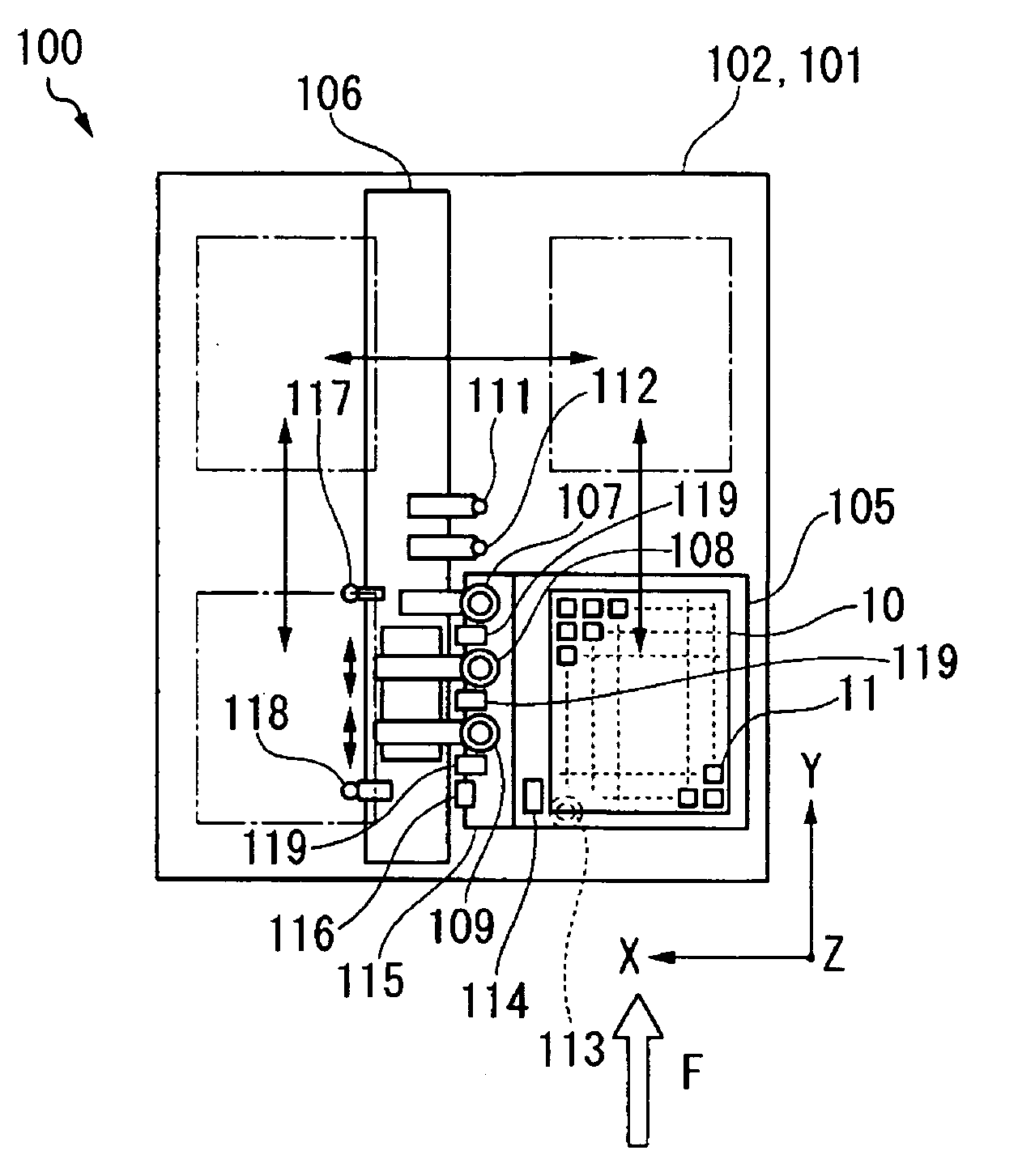
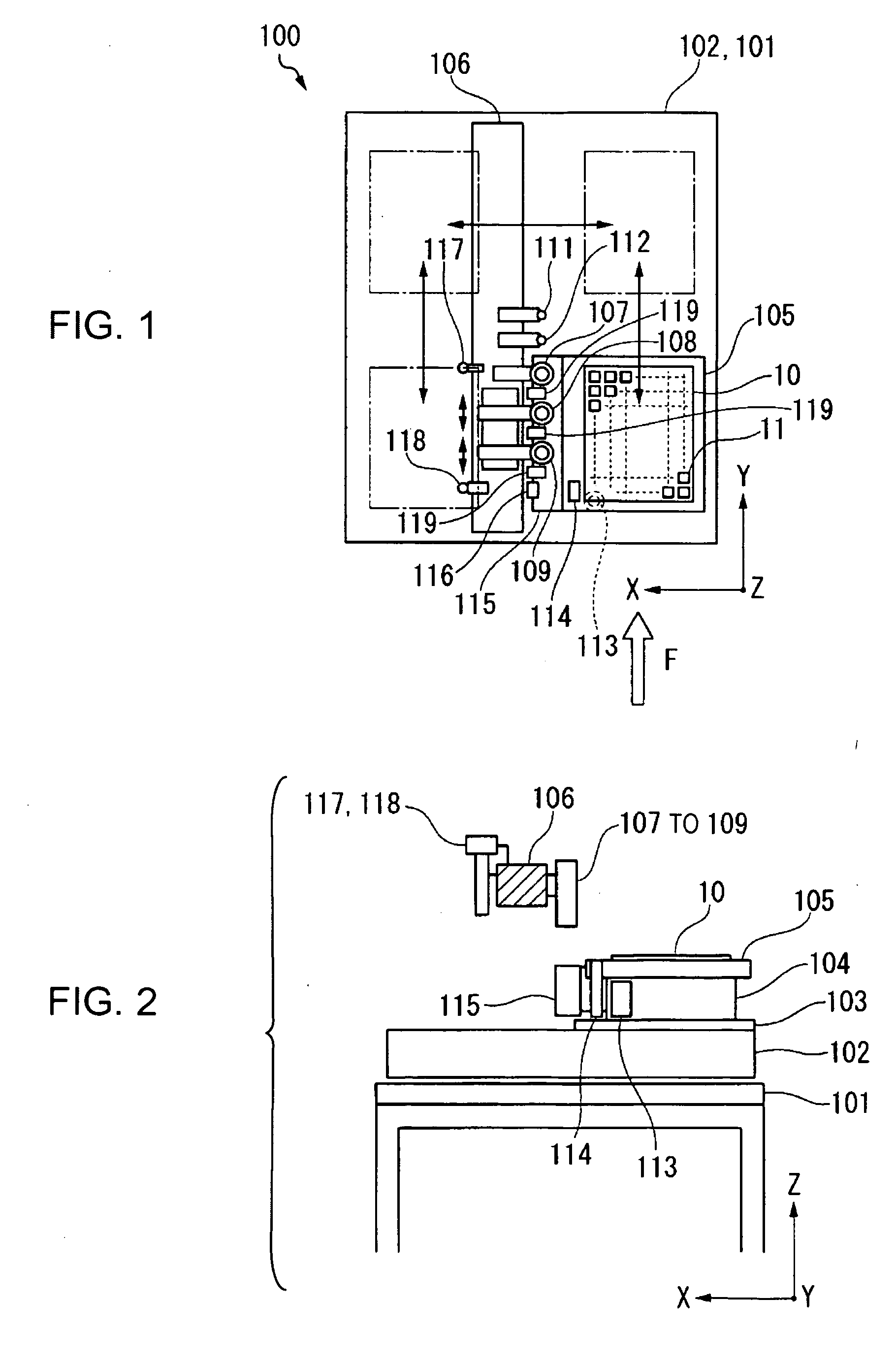
[0052]FIG. 1 is a schematic plan view showing a sealant drawing apparatus (a manufacturing apparatus of a liquid crystal device) according to an embodiment of the invention. FIG. 2 is a schematic explanatory view showing the arrangement construction of each of the elements of the apparatus in a height direction.

[0053] In the sealant drawing apparatus 100, an XY drive mechanism 102 (movement unit) is fixed to a support frame 101. An XY movement stage 103 (movement unit) is disposed to move on the XY drive mechanism 102 in a horizontal direction (i.e., an X direction and a Y direction). A θ drive mechanism 104 (movement unit) is fixed on the XY movement stage 103. A support table 105, which...


PUM


Abstract

A sealant drawing method is provided in which patterns for sealing an electro-optic material over a plurality of panel formation regions on a substrate are drawn by discharging sealant on the substrate from a nozzle of a coating unit, and which includes forming continuously first patterns on the plurality of panel formation regions in a batch manner, so as to form parts of the individual patterns in the plurality of panel formation regions; and forming continuously second patterns on the plurality of panel formation regions in a batch manner, so as to form the remainders of the individual patterns in the plurality of panel formation regions.

Description

BACKGROUND [0001] 1. Technical Field [0002] The present invention relates to a sealant drawing method, to a sealant drawing apparatus, and to a method and apparatus for manufacturing liquid crystal devices, and in particular, to a manufacturing technology suitable to a case where sealant with a high viscosity is used. [0003] 2. Related Art [0004] In general, in the process of manufacturing liquid crystal devices, a panel structure in which two substrates are adhered together using sealant and a liquid crystal material is enclosed therebetween is constructed. This manufacturing process includes a sealant coating process of forming a liquid crystal material enclosure region that contains a liquid crystal material by coating the sealant in such a way as to surround electrode patterns, such as transparent electrodes formed on an inner surface of the substrate. In the sealant coating method in this process, a screen-printing method has been widely used, especially, in the case where seal...

Claims


Application Information

Patent Timeline
IPC IPC(8): B05C5/00
CPCG02F1/133351G02F1/1339H01L21/67126
Inventor MURAKAMI, CHIHIRO
Owner 138 EAST LCD ADVANCEMENTS LTD
Learn More