
Method of forming contact pads

a technology of contact pads and contact pads, which is applied in the direction of photomechanical treatment, instruments, semiconductor devices, etc., can solve the problems of reducing the stability of the connection, oxidizing the contact pad, and adversely affecting the functionality of the semiconductor structur

Inactive Publication Date: 2006-06-29
GLOBALFOUNDRIES INC
View PDF2 Cites 130 Cited by
  • Summary
  • Abstract
  • Description
  • Claims
  • Application Information

AI Technical Summary

Benefits of technology

[0021] The following presents a simplified summary of the invention in order to provide a basic understanding of some aspects of the invention. This summary is not an exhaustive overview of the invention. It is not intended to identify key or critical elements of the invention or to delineate the scope of the invention. Its sole purpose is to present some concepts in a simplified form as a prelude to the more detailed description that is discussed later.

Problems solved by technology

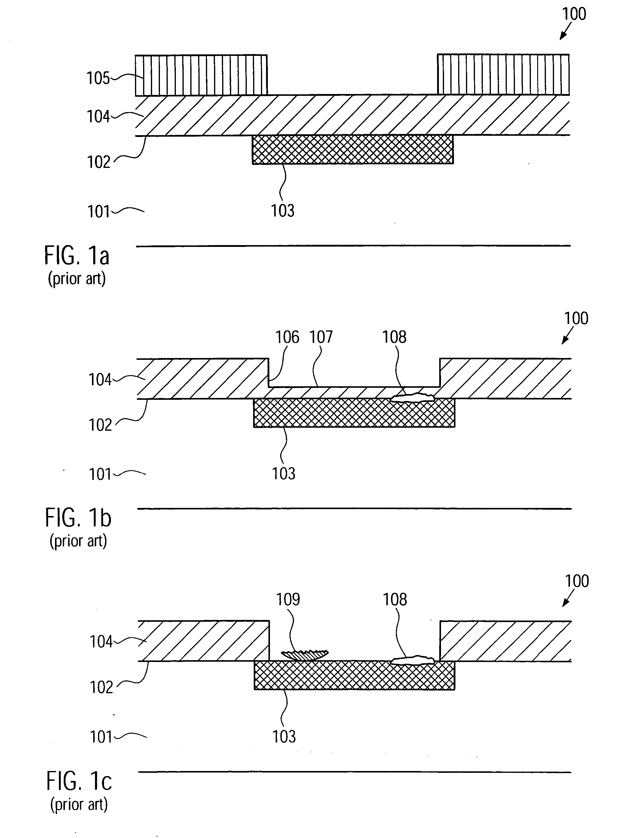
This flaking can adversely affect the functionality of the semiconductor structure 100.
A problem of the method of providing electrical contact to a semiconductor structure according to the state of the art is that, in the resist strip process, oxidized regions may form on the contact pad 103.
This may lead to a reduced stability of the connection.
Another problem of the method of providing electrical contact to a semiconductor structure according to the state of the art is that, in the second etching process, a flaking of layers of the semiconductor structure 100 may occur, which can adversely affect the functionality of the semiconductor structure 100.
Yet another problem of the method of providing electrical contact to a semiconductor structure according to the state of the art is that, in the second etching process, particles comprising by-products of chemical reactions may flake off the walls of the reaction vessels and can be deposited on the semiconductor structure.
Such cleaning processes, however, increase the downtime of the etching apparatus, which may adversely affect the production costs of semiconductor structures.

Method used


Image

  • Method of forming contact pads
  • Method of forming contact pads
  • Method of forming contact pads

Examples


Embodiment Construction

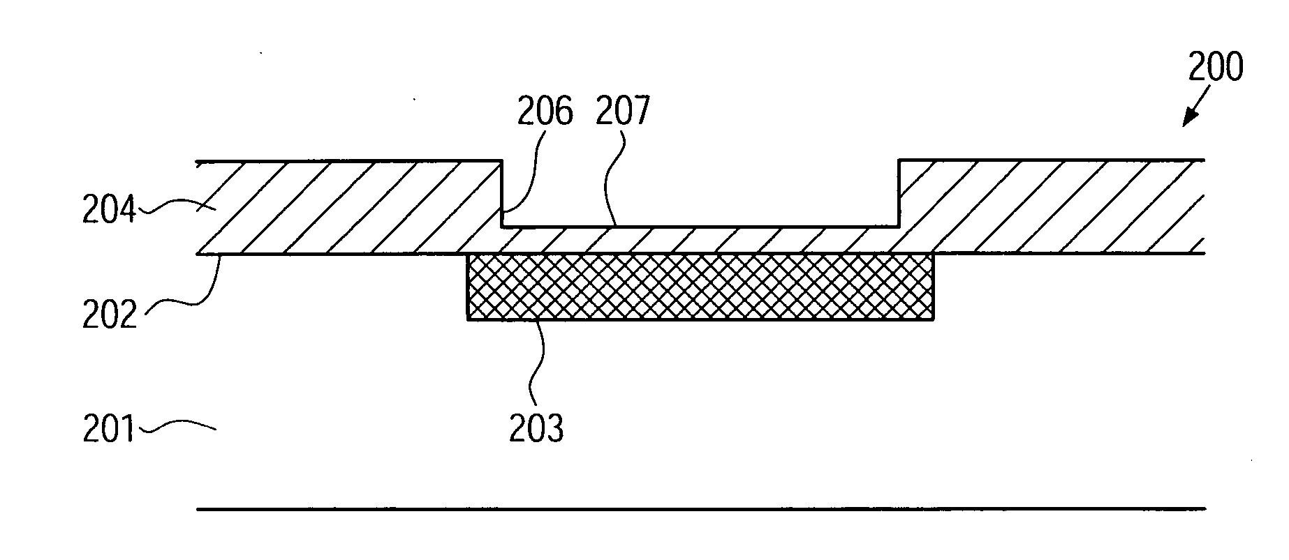
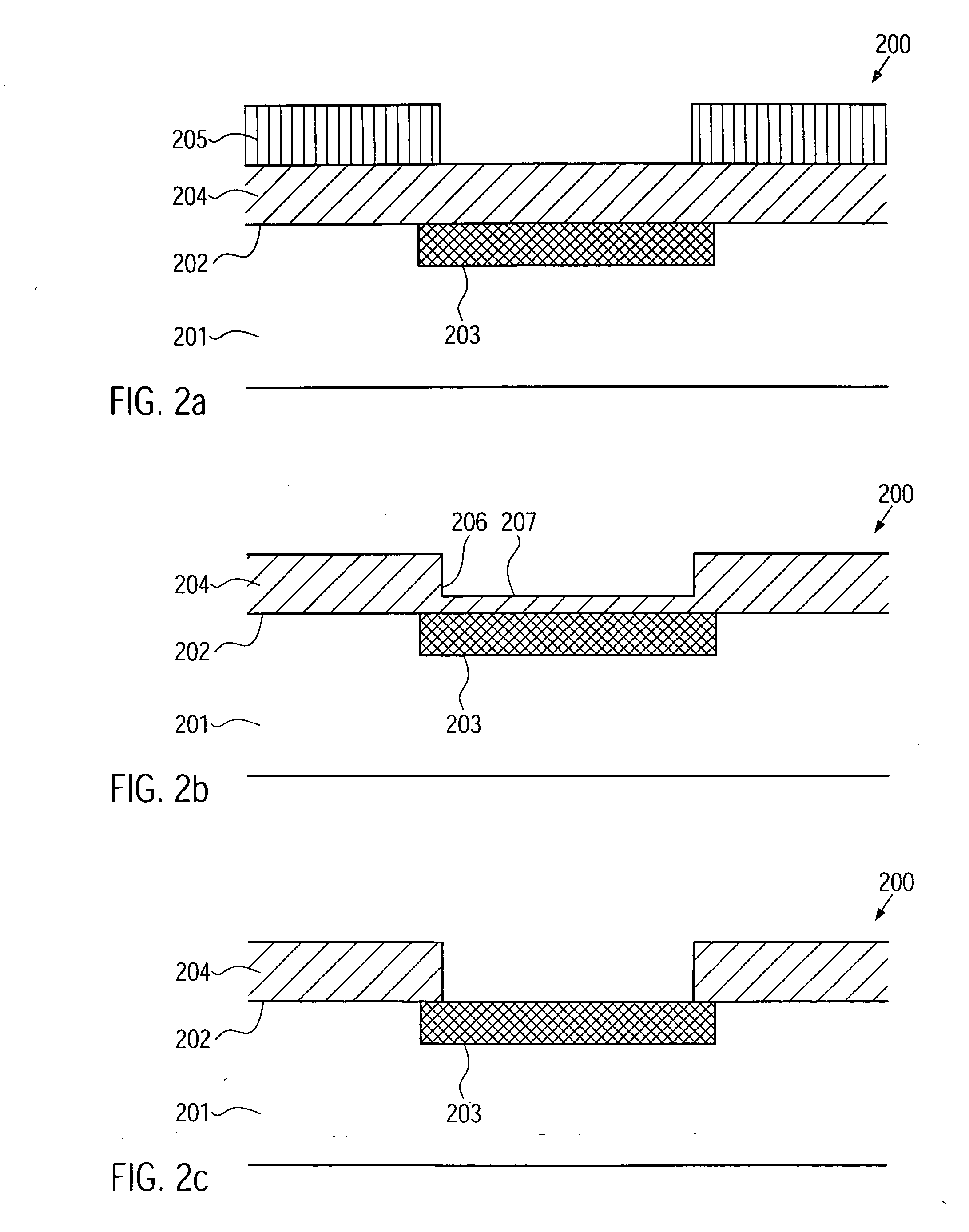
[0029] Illustrative embodiments of the invention are described below. In the interest of clarity, not all features of an actual implementation are described in this specification. It will of course be appreciated that in the development of any such actual embodiment, numerous implementation-specific decisions must be made to achieve the developers' specific goals, such as compliance with system-related and business-related constraints, which will vary from one implementation to another. Moreover, it will be appreciated that such a development effort might be complex and time-consuming, but would nevertheless be a routine undertaking for those of ordinary skill in the art having the benefit of this disclosure.

[0030] The present invention will now be described with reference to the attached figures. Various structures, systems and devices are schematically depicted in the drawings for purposes of explanation only and so as to not obscure the present invention with details that are we...


PUM


Abstract

In a method of forming a semiconductor structure, a substrate comprising at least one contact pad is provided. A passivation layer is formed over the substrate. A mask which does not cover a portion of the passivation layer located over the at least one contact pad is formed over the passivation layer. An etching process adapted to remove a material of the passivation layer is performed and the mask is removed. Then, a second etching process adapted to remove residues of the passivation layer from the contact pad can be performed. The removal of the mask may be performed at a temperature of the substrate in a range from about −20° C. to about 100° C. The second etching process can comprise exposing the substrate to a gaseous etchant comprising hydrogen and fluorine, an amount of hydrogen in the etchant being about equal to an amount of fluorine, or greater. Thus, a formation of oxides and / or fluorides on the at least one contact pad can be avoided.

Description

BACKGROUND OF THE INVENTION [0001] 1. Field of the Invention [0002] The present invention relates to the formation of integrated circuits, and, more particularly, to the formation of contact pads for providing electrical connections to a semiconductor structure. [0003] 2. Description of the Related Art [0004] Integrated circuits comprise a large number of individual circuit elements such as, e.g., transistors, capacitors and resistors formed on a substrate. These elements are connected internally by means of electrically conductive lines to form complex circuits, such as memory devices, logic devices and microprocessors. In order to accommodate all the electrically conductive lines required to connect the circuit elements in modern integrated circuits, the electrically conductive lines are arranged in a plurality of levels stacked on top of each other. In order to electrically connect the integrated circuit with other electronic components, input terminals and output terminals are p...

Claims


Application Information

Patent Timeline
Patent Type & Authority Applications(United States)
IPC IPC(8): H01L21/44H01L21/461
CPCG03F7/427H01L21/31116H01L21/31138H01L21/31144H01L21/76802H01L21/76834H01L24/11H01L2224/13099H01L2924/01027H01L2924/01029H01L2924/01074H01L2924/01078H01L2924/01079H01L2924/01082H01L2924/14H01L2924/19041H01L2924/19042H01L2924/19043H01L2924/01006H01L2924/01023H01L2924/01033H01L2924/01068H01L2924/01072H01L2924/014H01L2224/1134H01L2224/13144H01L2224/0557H01L2224/05573H01L2224/05647H01L2224/05571H01L2924/00014H01L2224/0554H01L2224/05599H01L2224/0555H01L2224/0556
Inventor NAUMANN, RONALDGRIMM, VOLKERMEINHOLD, TINO
Owner GLOBALFOUNDRIES INC
Features
  • Generate Ideas
  • Intellectual Property
  • Life Sciences
  • Materials
  • Tech Scout
  • Unparalleled Data Quality
  • Higher Quality Content
  • 60% Fewer Hallucinations
Learn More