Acoustic absorption system for an aircraft airframe

a technology of acoustic absorption and an aircraft, which is applied in the direction of aircraft crew accommodation, bandages, transportation and packaging, etc., can solve the problems of aircraft components generating vibration in the aircraft, noise may be a particular problem, and cabin noise, etc., and achieve the effect of reducing noise in the cabin of the aircra

Active Publication Date: 2006-07-06
SIKORSKY AIRCRAFT CORP
View PDF31 Cites 45 Cited by
  • Summary
  • Abstract
  • Description
  • Claims
  • Application Information

AI Technical Summary

Benefits of technology

[0008] An acoustic absorption system according to the present invention fills voids between airframe frame members within an airframe section with a close fitting foam portion. The foam portions are each interference or “force” fit into the voids to completely fill each of the frame voids. A mass barrier layer is adhered over the foam portions and to the multitude of frame members. The mass barrier layer is a contiguous layer adhered across the multitude of frame members to seal the airframe frame member voids to make use of mass-air-mass principles which reduce flanking path leakage around the foam portions.
[0009] The present invention therefore provides an effective lightweight acoustic absorption system which may be installed within an airframe for reducing noise within an aircraft cabin.

Problems solved by technology

Another source of cabin noise is airflow over various aircraft fuselage components.
These components generate vibrations in the aircraft that propagate through the airframe and radiate into the cabin.
Noise may be a particular problem in rotary wing aircraft cabins since the rotor and transmission systems produce a significant amount of vibration directly into the airframe structure.
The main noise problem in helicopter cabins is mid to high frequency gear whine noise from the main transmission.
This results in cabin noise vibrations typically from about 350 Hz through 4,000 Hz.
Disadvantageously, such batting is relatively heavy in weight and provides minimal noise attenuation within rotary wing aircraft due to inherent flanking path leakage around the batting coupled with the complex frequency structure and the intense amplitudes of the aircraft transmission gear noise signatures.

Method used


Image

  • Acoustic absorption system for an aircraft airframe
  • Acoustic absorption system for an aircraft airframe
  • Acoustic absorption system for an aircraft airframe

Examples


Embodiment Construction

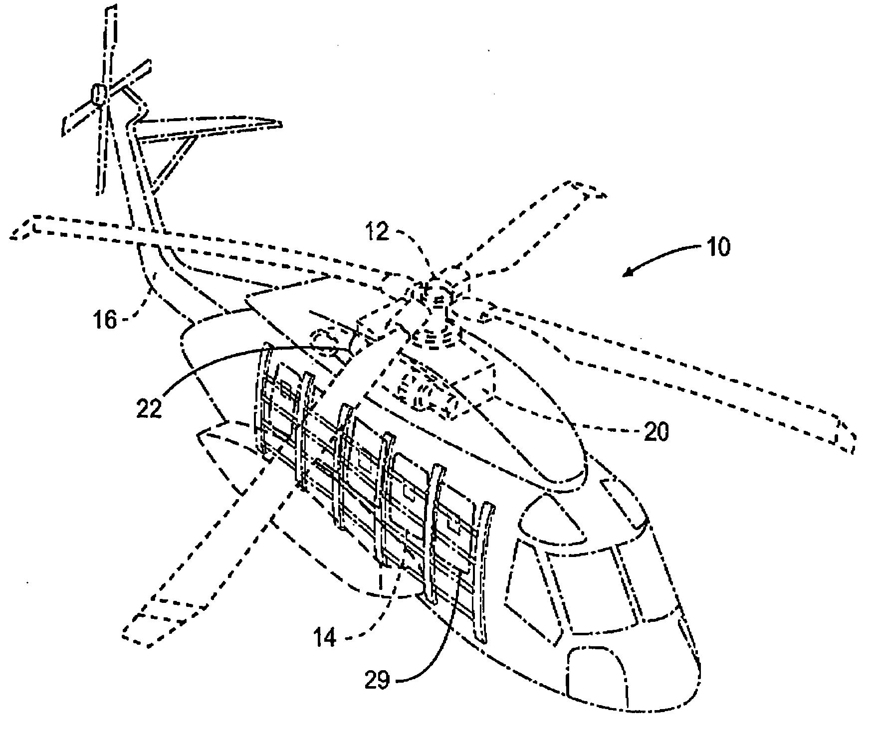
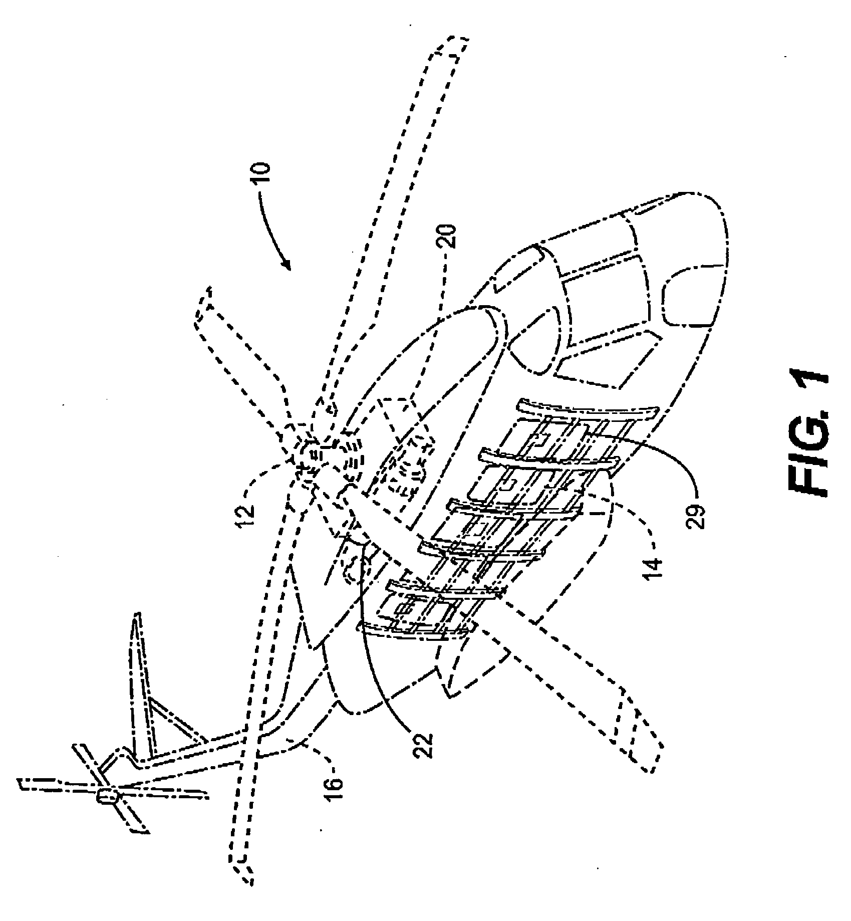
[0018]FIG. 1 schematically illustrates a rotary-wing aircraft 10 having a main rotor assembly 12. The aircraft 10 includes an airframe 14 having an extending tail 16 which mounts an anti-torque rotor 18. The main rotor assembly 12 is driven through a transmission (illustrated schematically at 20) by one or more engines 22. Although a particular helicopter configuration is illustrated in the disclosed embodiment, other machines such as turbo-props, tilt-rotor and tilt-wing aircraft will also benefit from the present invention.

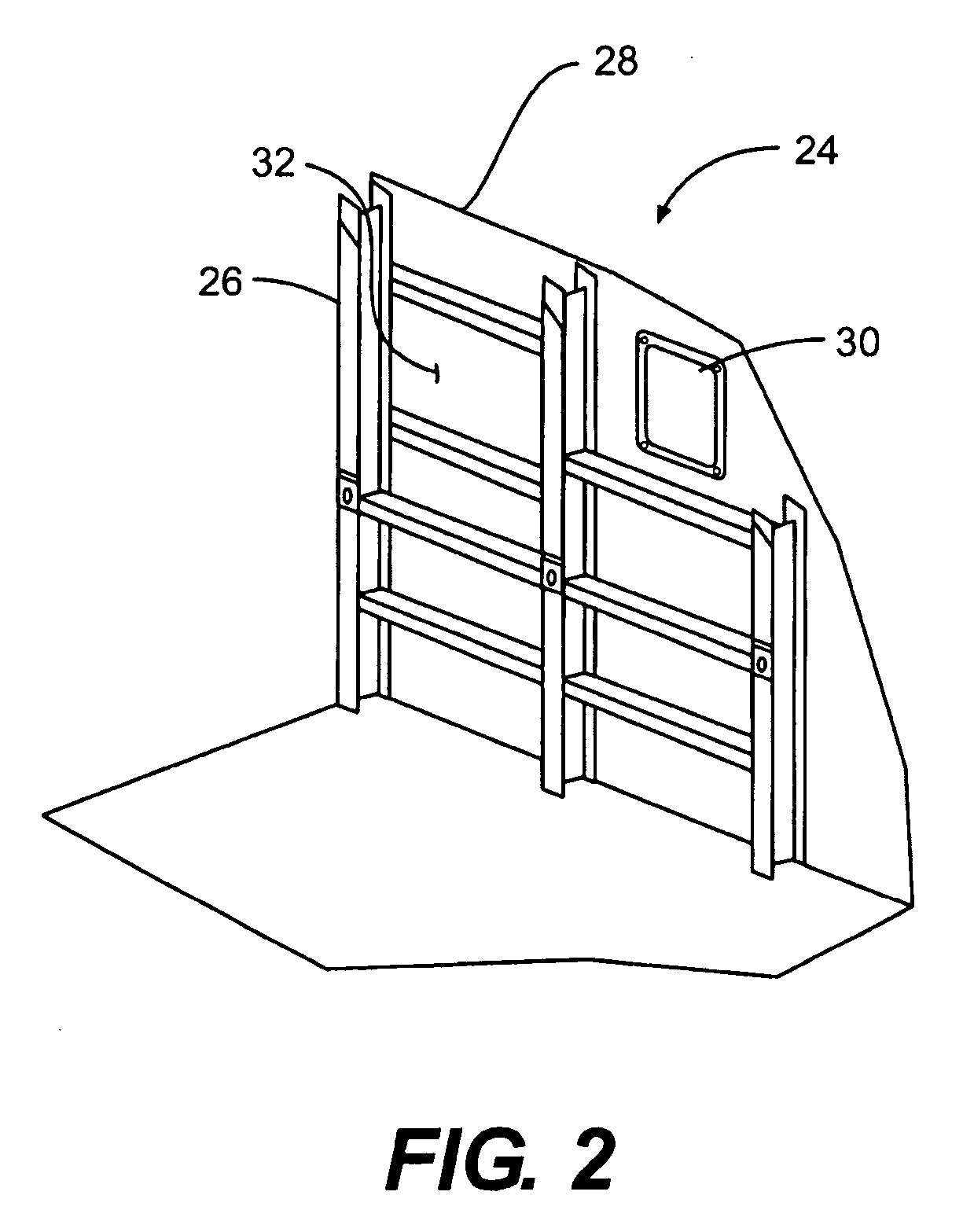
[0019] Referring to FIG. 2, an airframe section 24 within a cabin of the rotary wing aircraft includes a multitude of frame members 26 which support an outer skin 28. The airframe section 24 is the outer structure of the aircraft 10 and may include one or more window area 30. The window areas 30 are typically located through the outer skin 28 between the multitude of frame members 26. The multitude of frame members 26 are typically arranged in a rectilinear pat...


PUM


Abstract

An acoustic absorption system fills each frame void within an airframe section with a close fitting foam portion. A mass barrier layer is adhered over the foam portions and to a multitude of frame members. The mass barrier layer is a contiguous layer adhered across the multitude of frame members to seal the airframe frame voids to make use of mass-air-mass principles to reduce flanking path leakage around the foam portions.

Description

BACKGROUND OF THE INVENTION [0001] The present invention relates to a noise reduction treatment for an aircraft cabin, and more particularly to a lightweight acoustic absorption system which is mounted within an airframe subcomponent to reduce aircraft interior noise levels. [0002] Noise develops in an aircraft cabin from several sources. The most common sources are internally or externally mounted moving components, such as a transmission, engine or rotor system. Another source of cabin noise is airflow over various aircraft fuselage components. These components generate vibrations in the aircraft that propagate through the airframe and radiate into the cabin. [0003] Noise may be a particular problem in rotary wing aircraft cabins since the rotor and transmission systems produce a significant amount of vibration directly into the airframe structure. This problem may be more pronounces in rotary wing aircraft than in fixed wing aircraft inasmuch as the dynamic components on a rotary...

Claims


Application Information

Patent Timeline
Patent Type & Authority Applications(United States)
IPC IPC(8): B64D11/00
CPCB64C1/066Y10T428/233B64C1/40
Inventor DROST, STUART K.
Owner SIKORSKY AIRCRAFT CORP
Why Eureka
Try Eureka