
Alternator for a vehicle

a technology of alternators and vehicles, applied in the field of alternators, can solve the problems of unallowable weakening of the capability of the conductor, the inability to remove or reduce the thickness of the insulator film, and the serious suppression of the thermal dissipation of the conductor, so as to improve the resistance to electrolytic corrosion and efficient conductivity. , the effect of improving the insulation capability of the coil

Inactive Publication Date: 2006-07-06
MITSUBISHI ELECTRIC CORP
View PDF14 Cites 14 Cited by
  • Summary
  • Abstract
  • Description
  • Claims
  • Application Information

AI Technical Summary

Benefits of technology

[0005] The present invention has been made in order to solve the above-described problem, and it is an object thereof to obtain an ac generator for a vehicle which can ensure insulation capability between coils and can achieve downsizing and high-powering or improvement in the insulating capacity and electrolytic corrosion resistibility without a necessity of separately disposing each conductor in space.
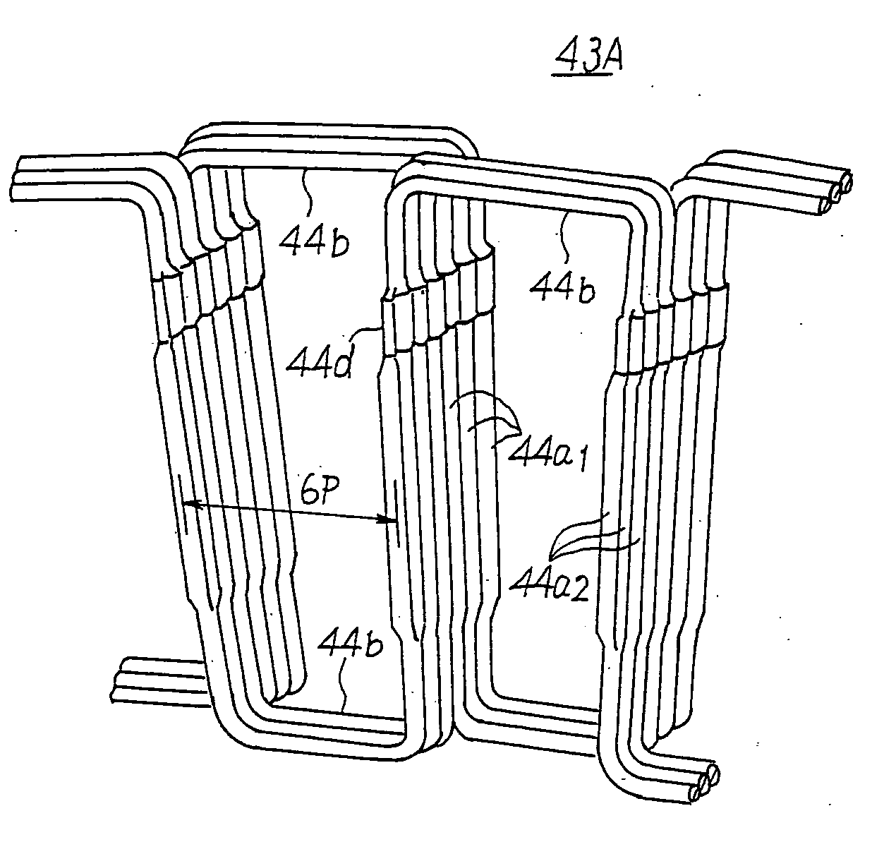
[0007] According to the present invention, as an ac generator for a vehicle is constituted so that the shape of conductors in the slot-in portions located in the slot is substantially rectangular in its cross section and the thickness in insulation layers of that portions is smaller than the other portion, there are advantages that heating from the conductors can be efficiently conducted to the laminated core and the housing.
[0008] On the contrary, the thickness in insulating layers of the cross-over portions is larger than the other, insulation capability among the coils is assured and the axial height of the cross-over portion can be lowered to prevent conductors of the cross-over portion from water immersion, improving electrolytic corrosion resistibility without disposing unnecessary space among coils.

Problems solved by technology

In the conventional stator, generally, it was well known that electric conductors coated with insulator films have been widely used, and the insulator films cause thermal dissipation of the conductors to seriously suppress to low levels.
However, it is practically impossible for the insulator films to be removed or made smaller in thickness because the insulation capability of the conductors will be unallowably weakened.

Method used


Image

  • Alternator for a vehicle
  • Alternator for a vehicle
  • Alternator for a vehicle

Examples


embodiment 1

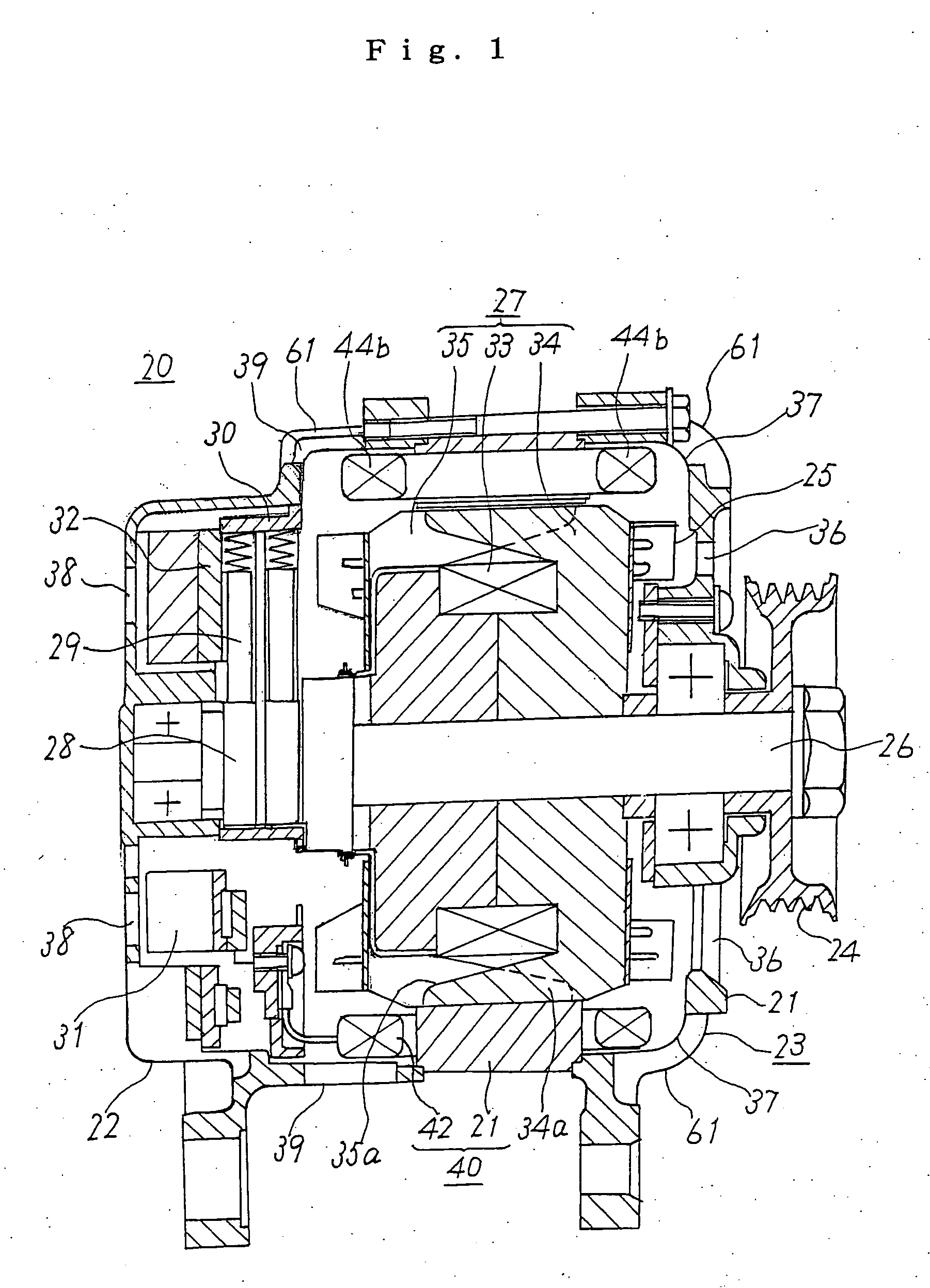
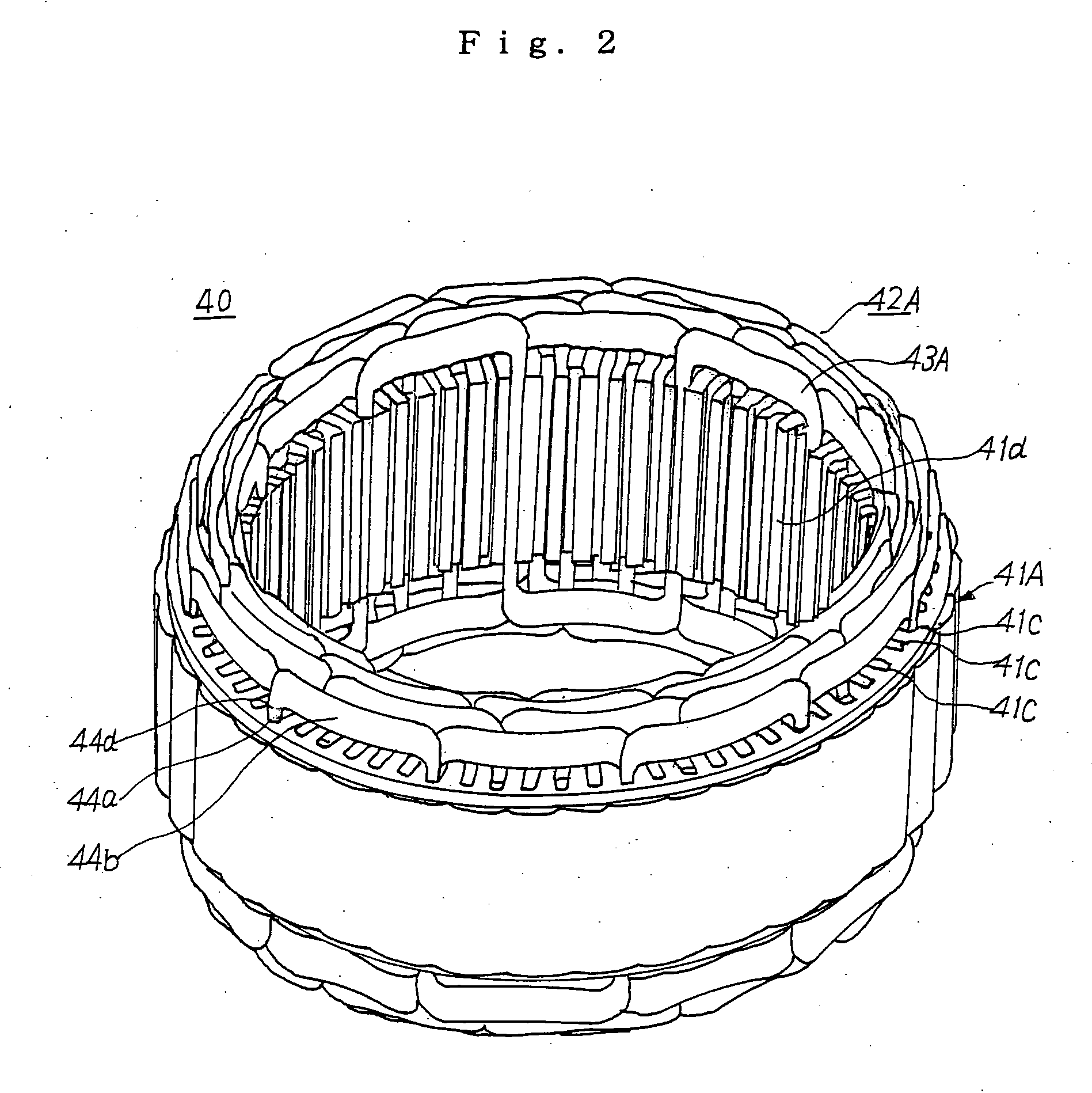
[0019] An ac generator for a vehicle of a first embodiment of the invention will be described referring to FIG. 1. As shown in FIG. 1, the ac generator for a vehicle 20 is provided with a housing 23 comprising of a front bracket 21 and a rear bracket 22 each of which is constructed in a bowl-shape and made of aluminum of good heat conductance, a shaft 26 installed in the housing 23 and on one end of which a pulley 24 is fixed, a Randell type rotor 27 secured on the shaft 26, a fan 25 secured on both ends of the axis of the rotor 27, a stator 40 fixed on the housing 23 so as to surround the rotor 27, a slip-ring 28 fixed on the other end of the shaft 26 to serve a current to the rotor 27, a pair of brushes 29 sliding over the surface of the slip-ring 28, a brush holder 30 for storing the brushes 29, a rectifier 31 electrically connected to the stator 40 for rectifying an alternative current generated by the stator 40 into a direct current, and a regulator 32 fixedly inserted to the b...

embodiment 2

[0029] According to the second preferred embodiment, as shown in FIG. 6, before the slot-in portions 44a of the winding unit is installed in the slot 41c, the slot-in portions 44a of the conductor 44 is molded to substantially rectangular shape in cross section having a shorter side thereof in the radial direction and a longer side thereof in the circumferential direction of the generator, and are drawn up circumferentially in two lines closely each other. In FIG. 6, reference numeral 47 represents insulating resins impregnated in the slot 41c to mold the winding unit.

The above mentioned construction enables the slot-in portions 44a of the conductor 44 to be installed in the slot 41c with no space each other circumferentially.

[0030] According to the second embodiment, therefore, as the electrical conductors are closely laminated in the radial direction at the longer side of the rectangular rod at which the insulating coating is kept thin in the circumferential direction, it is al...

embodiment 3

[0031] According to the third preferred embodiment, as shown in FIG. 7, before the slot-in portions 44a of the winding unit is installed in the slot 41c, the slot-in portions 44a of the conductor 44 is molded to substantially rectangular shape in cross section having a longer side thereof in the radial direction of the generator and a shorter side thereof in the circumferential direction, and are drawn up in the radial direction in one lines closely each other.

[0032] The above mentioned construction enables the slot-in portions 44a of the conductor 44 to be installed in the slot 41c with no space each other circumferentially.

[0033] According to the third embodiment, therefore, as a heat conductive surface between the longer side of the rectangular rod at which insulating coating is kept thin in the radial direction and the dents of teeth of the laminated core are kept widely, it is also possible to effectively dissipate heat generated by armature windings to the periphery the lami...


PUM

PropertyMeasurementUnit
thicknessaaaaaaaaaa
diameteraaaaaaaaaa
thicknessaaaaaaaaaa

Abstract

An ac generator for a vehicle is constituted so that the thickness in insulation layers of conductors in the slot-in portions located in the slot is smaller than the other to permit a metal portion of conductors to be much larger and to increase a density of conductors in the slots, causing heating from electrical conductors to efficiently conduct to a laminated core and a housing. On the contrary, the thickness in insulating layers of the cross-over portions is larger than the other to assure insulation capability among the coils and to prevent conductors of the cross-over portion axially exposed from the core to air from water immersion to improve an electrolytic corrosion resistibility without disposing unnecessary space among coils.

Description

TECHNICAL FIELD [0001] The present invention relates to an ac generator driven by, for example, an internal combustion engine, in particular, to a stator construction of the ac generator loaded in a vehicle such as a passenger car, a truck or the like. BACKGROUND OF THE INVENTION [0002] In an ac generator for a vehicle, requirement for downsizing and high-powering, or for an enhanced insulation performance and an electrolytic corrosion tolerance have been recently increasing, and a variety of improved approaches to fulfill those requirements have been proposed. [0003] With respect to an improvement of a power generation capacity, as described in JP H11-164505, an improved construction in which each of the electrical conductors is separately disposed in space one another and a thickness in insulating layers in a cross-over portion of electric conductors is set smaller than that in a slot-in portion located in slots, has been proposed in order to improve cooling capabilities in the cr...

Claims


Application Information

Patent Timeline
Patent Type & Authority Applications(United States)
IPC IPC(8): H02K1/00H02K23/26H02K15/14H02K3/12H02K3/28H02K3/34H02K3/38H02K3/44
CPCH02K3/12H02K3/34H02K3/345Y10T29/49073H02K3/44Y10T29/49009H02K3/38
Inventor KASHIHARA, TOSHIAKITANAKA, KAZUNORIOHNISHI, YUKIYOSHITAMURA, SYUICHIOHTA, YOSHIKAZU
Owner MITSUBISHI ELECTRIC CORP
Learn More