Network relay device, network relay program, and recording medium containing the network relay program

a network relay and relay program technology, applied in multiplex communication, data switching networks, wireless commuication services, etc., can solve the problems of unfavorable smooth proliferation of the system as described above, unfavorable user experience, and inability to release band properly, so as to facilitate the introduction of a wider communications network

Inactive Publication Date: 2006-07-06
SHARP KK
View PDF19 Cites 32 Cited by
  • Summary
  • Abstract
  • Description
  • Claims
  • Application Information

AI Technical Summary

Benefits of technology

[0014] That is, for example, for data transmission from a data transmitting station on the first communications network to a data receiving station on the second communications network, the data transmitting station first transmits, to the network relay device, a signal indicating that the data transmitting station is going to transmit data. This signal may be a signal normally used in the first communications network, so that it is not necessary for the data transmitting station to perform a special operation.
[0015] Then, on the network relay device, the event / state detecting section detects this signal from the data transmitting station as the event regarding the first communications network. On the basis of a calculation result obtained by the communications resource determination section, the communications resource management section obtains a communications resource in the second communications network. In this manner, communications with the data receiving station becomes possible. Here again, it is not necessary for the data receiving station to perform a special operation.
[0016] As described above, according to the above arrangement, for communications between communications stations respectively provided in communications network of mutually different types, it is not necessary for both of the communications stations to perform special operations. Therefore, it is possible to use conventional devices as they are. This brings about the effect of allowing the user to easily introduce a wider communications network including communications networks of mutually different types.

Problems solved by technology

This puts an enormous load on users, and a smooth proliferation of the system as described above cannot be expected.
That is, in the wireless network, there arises the problem that it is necessary to secure a band in consideration with a property of wireless communications.
However, on the wireless network side, a band is not released properly since such a disconnection in the communications is unexpected.
This causes the problem of a waste of a band.
Moreover, in the above system, there arises the problem that if securing of a band in the IEEE1394 wired network has succeeded, but securing of a band in the wireless network has failed, it is impossible to release a band in the wired network.

Method used


Image

  • Network relay device, network relay program, and recording medium containing the network relay program
  • Network relay device, network relay program, and recording medium containing the network relay program
  • Network relay device, network relay program, and recording medium containing the network relay program

Examples


first embodiment

[0037] One embodiment of the present invention is described below with reference to FIGS. 1 through 5, and FIGS. 14 and 15.

[0038] (1-1. Network Structure)

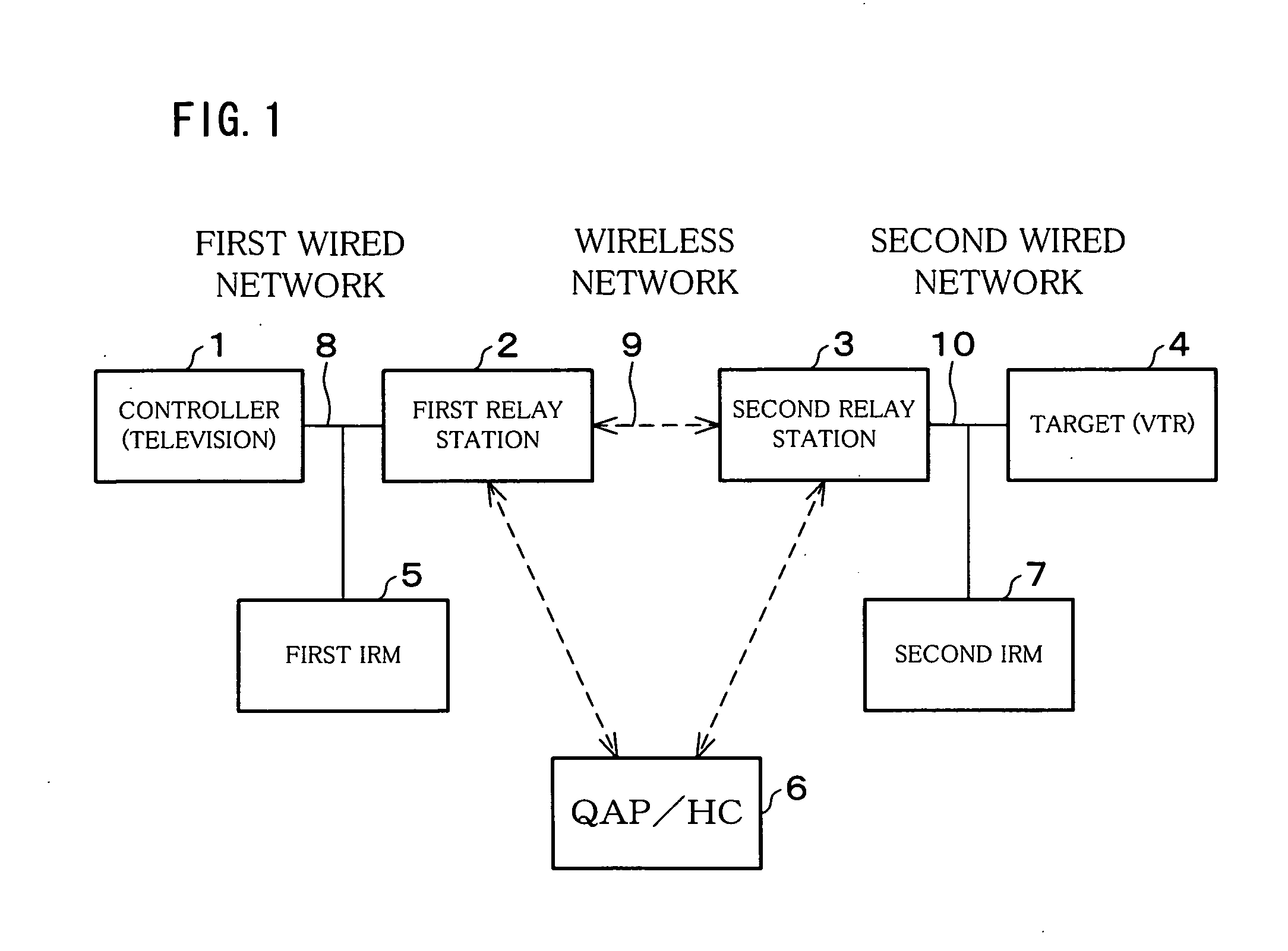
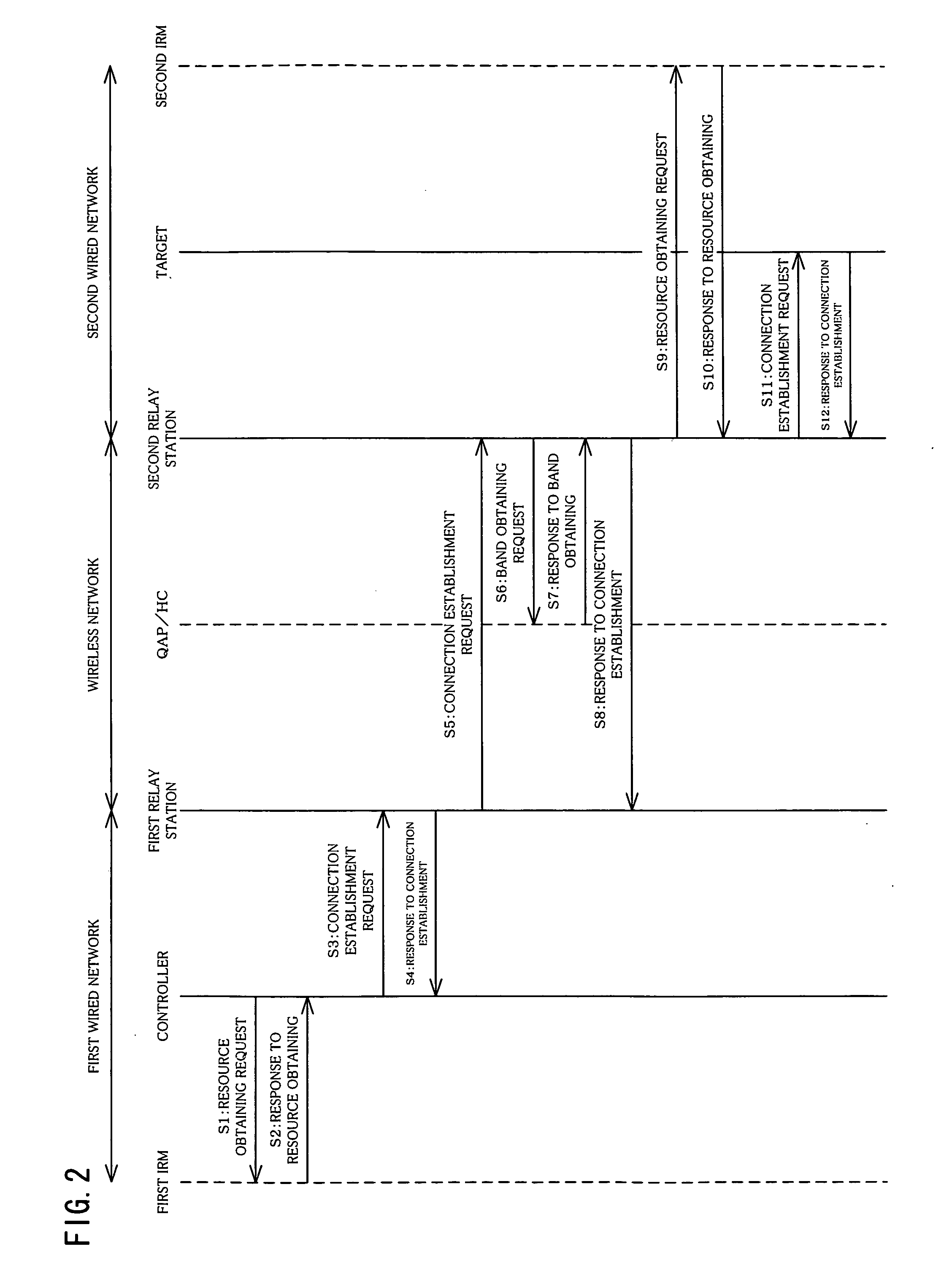
[0039]FIG. 1 is a block diagram illustrating a schematic structure of a communications network system according to the present embodiment. As illustrated in FIG. 1, this communications network system includes a controller 1, a first relay station (network relay device) 2, a second relay station (network relay device) 3, a target 4, a first IRM (Isochronous Resource Manager) 5, a second IRM 7, and a QAP / HC 6.

[0040] The controller 1, the first relay station 2, and the first IRM 5 are connected to one another via a first wired network 8, which provides a first wired network system. Further, the second relay station 3, the target 4, and the second IRM 7 are connected to one another via a second wired network 10, which provides a second wired network system. In the present embodiment, the first and second wired network systems are as...

second embodiment

[0094] The following will describe one embodiment of the present invention with reference to FIGS. 6 and 7. Note that, members having the same functions as those described in the First Embodiment are given the same reference numerals and explanations thereof are omitted here.

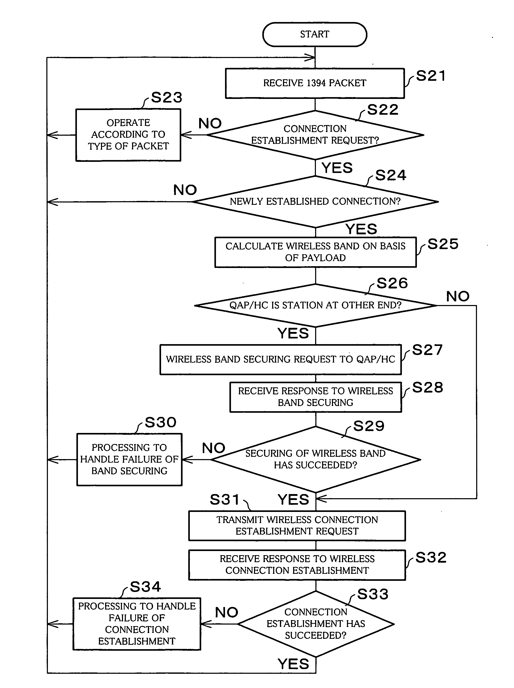
[0095] In the First Embodiment, taken as an example is a case where the relay station detects an operation for obtaining or release of a band on one network, after which it obtains or releases a band on the other network. In the present embodiment, taken as an example is a case where the relay station detects a stream transmitted through one network, after which it obtains a band on the other network. Specifically, taken as an example is a case where the second relay station 3 receives a stream through the second wired network 10, after which it obtains a band on the wireless network 9.

[0096] (2-1. Structure of Relay Device)

[0097]FIG. 6 is a block diagram illustrating a schematic structure of the relay statio...

third embodiment

[0111] The following will describe one embodiment of the present invention with reference to FIGS. 8 and 9. Note that, members having the same functions as those described in the foregoing Embodiments are given the same reference numerals and explanations thereof are omitted here.

[0112] In the present embodiment, taken as an example is a case where while a relay station transfers a stream transmitted from one network to another network, only a band obtained on the network concerned is changed depending upon a transfer state of another network. Specifically, taken as an example is a case where while the second relay station 3 transfers a stream having been received from the second wired network 10 to the wireless network 9, a band to be obtained on the wireless network 9 is changed.

[0113] (3-1. Structure of Relay Device)

[0114]FIG. 8 is a block diagram illustrating a schematic structure of the relay station 21 according to the present embodiment. Note that, the following descriptio...


PUM


Abstract

When a wired connection detecting section 27 receives a connection establishment request from a wired network, a band conversion section 28 calculates a bandwidth required for wireless communications on the basis of bandwidth information obtained from communications in the wired network. Then, on the basis of the bandwidth calculated, the wireless resource management section 30 secures a communications resource in a wireless network.

Description

TECHNICAL FIELD [0001] The present invention relates to a network relay device for relaying between different types of communications networks. BACKGROUND ART [0002] In recent years, digitalization in home-AV (Audio / Visual) devices has been promoted. As for television, for example, transition from terrestrial broadcasting to digital has been planed as well as transition from satellite broadcasting to digital. In addition, DVD (Digital Versatile Disc) home theater systems have been widely used. Moreover, with the development of communications infrastructures, broadband Internet connections have been progressed, and such a video distribution that high-quality video data are received through streaming via this broadband Internet has been developed for its practical use. [0003] Thus, under circumstances where various AV devices are provided in a house, demanded is a usage pattern of the AV devices where these AV devices are connected through a network so that they operate in conjunction...

Claims


Application Information

Patent Timeline
Patent Type & Authority Applications(United States)
IPC IPC(8): H04Q7/24H04J3/22H04L12/28H04L12/40H04L12/46H04W24/00H04W28/16H04W72/04H04W76/02H04W88/04H04W92/02H04W92/16
CPCH04L12/40065H04L12/4011H04L12/5695H04L47/14H04L47/15H04L47/748H04L47/762H04L47/824H04L47/829H04W28/16H04W76/02H04W88/04H04W92/02H04W76/10H04L12/40052H04L47/83H04L47/70H04W8/04
Inventor TAKEMOTO, MINORUUEDA, TORU
Owner SHARP KK
Why Eureka
Try Eureka