Fiber optic temperature sensor

Inactive Publication Date: 2006-07-06
TRUSTEES OF BOSTON UNIV
View PDF7 Cites 39 Cited by
  • Summary
  • Abstract
  • Description
  • Claims
  • Application Information

AI Technical Summary

Benefits of technology

[0008] In accordance with the present invention, a fiber optic temperature sensor and system are disclosed that achieve the benefits of optical temperature sensing

Problems solved by technology

However, the maximum temperatures in these processes can reach as high as 1,700 to 2,300° C. Ordinary thermo

Method used


Image

  • Fiber optic temperature sensor
  • Fiber optic temperature sensor
  • Fiber optic temperature sensor

Examples


Embodiment Construction

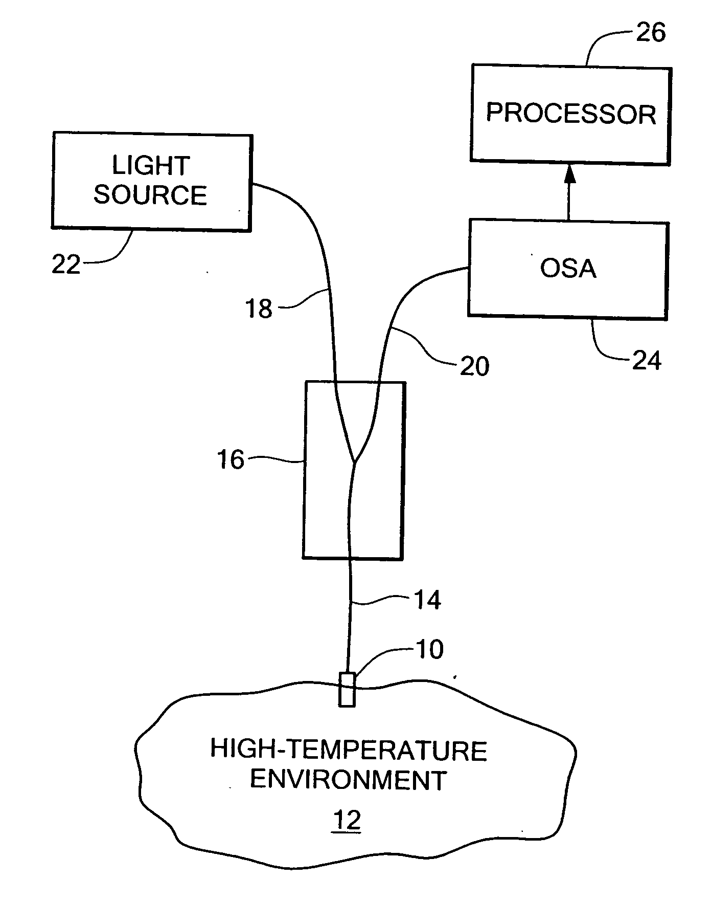
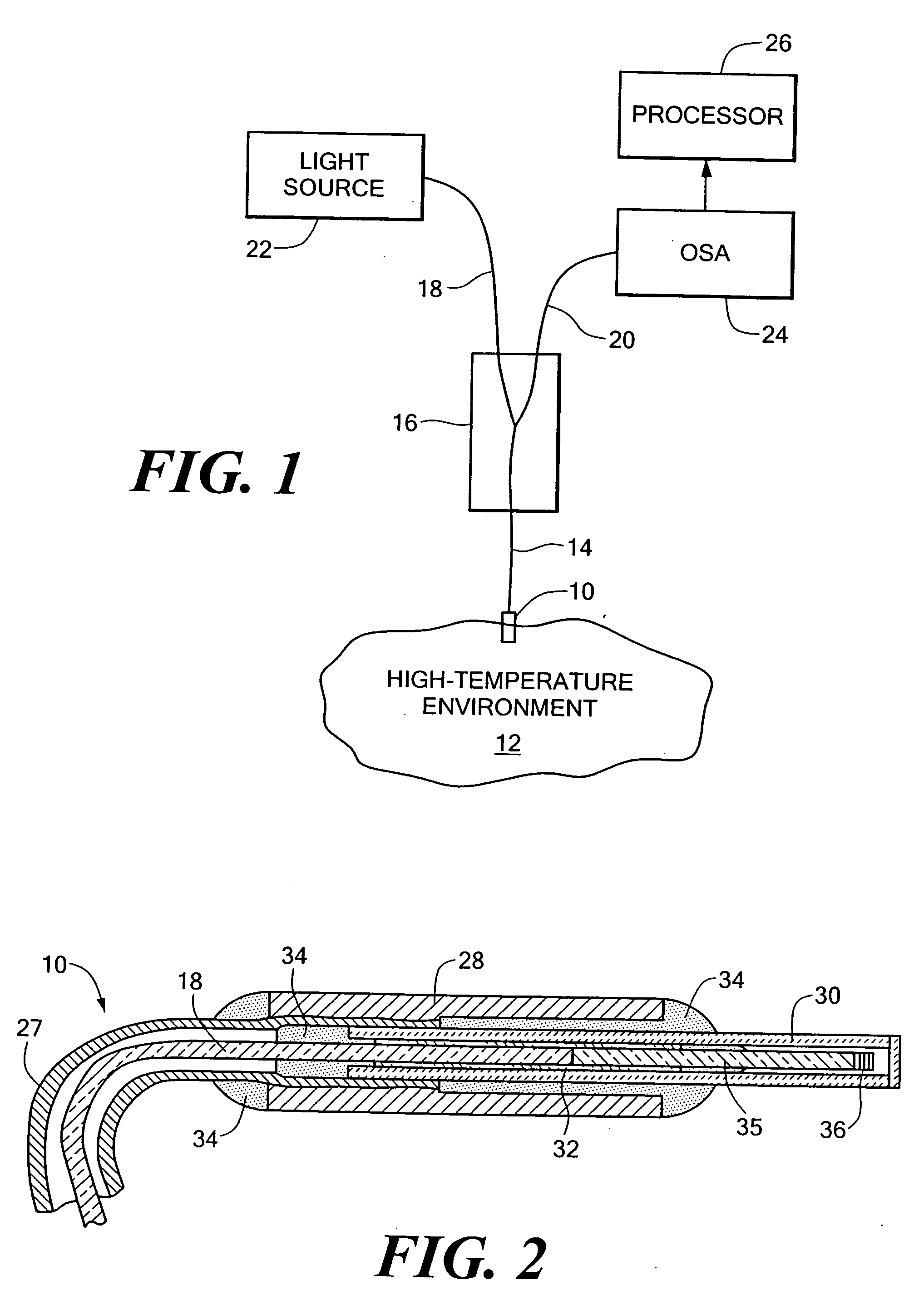
[0019]FIG. 1 illustrates a temperature measurement system employing an optical-fiber-based probe 10 disposed in a high-temperature environment 12. The high-temperature environment 12 may exhibit a temperature range from −200° C. to 2,350° C., the upper end of which is considerably higher than the maximum temperatures that may be directly measured using conventional means. Examples of such high-temperature environments 12 include material processes (such as the manufacture of ceramics), gas turbine inlet streams (such as jet engines or power plants), rocket nozzle exhaust streams, and space applications, etc.

[0020] Extending from the probe 10 is an optical fiber 14. An optical coupler 16 joins the probe fiber 14 to two additional fibers 18, 20. The fiber 18 carries light from a broadband light source 22 to the probe 10 via the coupler 16, and the fiber 20 carries reflected light from the probe 10 to an optical spectrum analyzer (OSA) 24, which may be for example a charge-coupled dev...


PUM


Abstract

A fiber optic temperature sensor (10) and system employ optical (fiber 34) and a fiber Bragg grating (36) using non-silica materials that can withstand temperature ranges extending well above the silica-imposed limit of 1,100 degrees C. The system measures the wavelength shift of light reflected from the fiber Bragg grating (36) and converts it into a temperature value. Specific optical fibers include sapphire, which can be used at temperatures approaching 1,800 degrees C., and yttria-stabilized zirconia (YSZ), which can be used at temperature in excess of 2,300 degrees C. One specific grating employs alternating layers of YSZ, with the percentage of yttria varying in the alternating layers to achieve the desired difference of refractive index, and another grating employs alternating layers of alumina and zirconia.

Description

CROSS REFERENCE TO RELATED APPLICATIONS [0001] This application claims priority under 35 U.S.C. §119(e) of U.S. Provisional Patent Application No. 60 / 428,099 filed Nov. 21, 2002, the disclosure of which is hereby incorporated by reference herein.STATEMENT REGARDING FEDERALLY SPONSORED RESEARCH OR DEVELOPMENT [0002] This invention was made with Government support under contract no. N00014-97-G011 awarded by the Department of the Navy, and from the Air Force Office of Scientific Research, under contract number ______. The Government has certain rights in the invention.BACKGROUND OF THE INVENTION [0003] The present invention relates to the field of temperature measurement devices and techniques based on optical technology. [0004] In many high temperature processes, it is important to have accurate knowledge of temperature, for example to maximize efficiency. This is true for processes such as materials processing in the metal and glass industries, and is equally true in the measurement...

Claims


Application Information

Patent Timeline
IPC IPC(8): G01J5/00G01K11/32G02B6/02G02B6/26
CPCG01J3/1895G01J5/0088G01J5/024G01J5/026G01J5/041G01J5/046G01J5/048G01J5/08G01J5/0803G01J5/0821G01J5/602G01K11/3206G01K11/3213G02B6/02061G02B6/021G02B6/0219G02B6/2558
Inventor MORSE, THEODOREFLUO, FEI
Owner TRUSTEES OF BOSTON UNIV
Why Eureka
Try Eureka