Thin film tube reactor

Inactive Publication Date: 2006-07-06
NANODYNAMICS INC
View PDF18 Cites 11 Cited by
  • Summary
  • Abstract
  • Description
  • Claims
  • Application Information

AI Technical Summary

Benefits of technology

[0012] An advantage of the present invention is that the rotating tube creates a thin film of process components for a continuous reaction.
[0013] A further advantage of the present invention is that the separation of components in the film occurs in the outlet section of the invention to minimize downstream processing. Also, the separation reservoir may be integral with the reactor such that the invention provides a continuous reaction and separation in a single enclosed module. A particular advantage of an integral separation reservoir is that as the products are removed from the system, unspent reactants continue to react to form additional products, thereby reducing the waste of unspent reactants.
[0014] An even further advantage of the present invention is that the thin film has a low thermal inertia for rapid temperature changes and allows simplified exposure to electromagnetic fields. The thin film further allows all constituent components to be rapidly mixed on the molecular level and the shear stresses applied to the thin film by the rotating tube further promote mixing. The thin film has a large surface area and therefore there is excellent contact between a gaseous component and the film.
[0015] A still further advantage of the present invention is that several tube reactors may be connected in series wherein the separate tube reactors may have different processing parameters such as angular velocity and diameter.

Problems solved by technology

A common problem in chemical reaction processes is how to achieve the proper hydrodynamics in the reactor to efficiently produce the desired products.
In some cases rapid temperature changes are desired though difficult to achieve due to the thermal inertia of the reaction components.
Also, it is often difficult to ensure proper saturation of the reaction components by an electromagnetic field as the outermost portion of the mixture of reactants tends to be exposed to more radiation than the innermost portion.
However, these coats tend to suffer from attrition and will inevitably deactivate with time.
Best uses gas pressure modulation to maintain the thin film and thus does not rotate the tube to provide or maintain the thin film nature of the liquid phase of the reaction.
Further, Best does not provide for the separation of multiple products in an integrated separation reservoir.

Method used


Image

  • Thin film tube reactor
  • Thin film tube reactor
  • Thin film tube reactor

Examples


Embodiment Construction

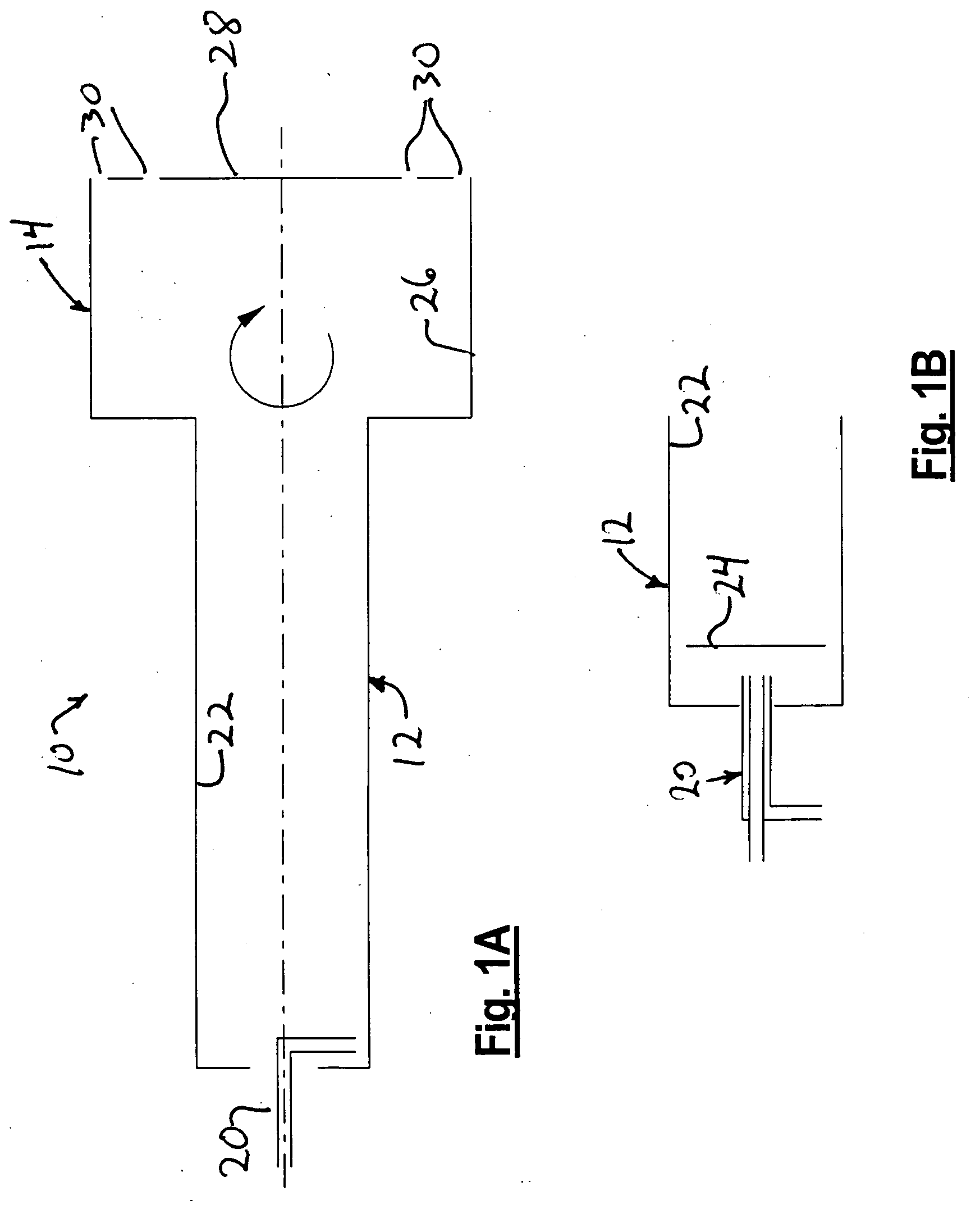
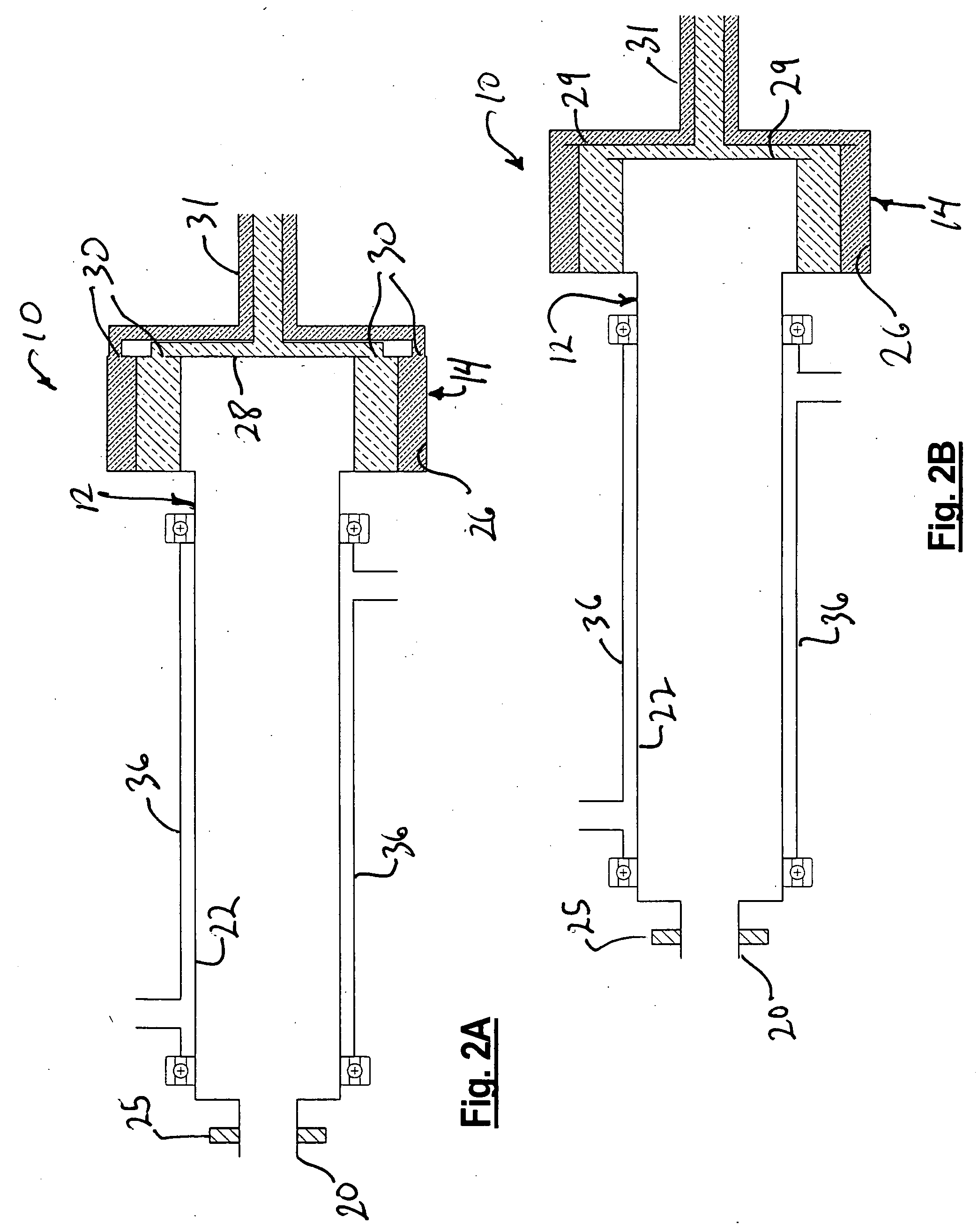
[0027] Referring to FIG. 1A, there is shown the thin film tube reactor of the present invention. The tube reactor 10 includes a primary tube 12, and a separation reservoir 14.

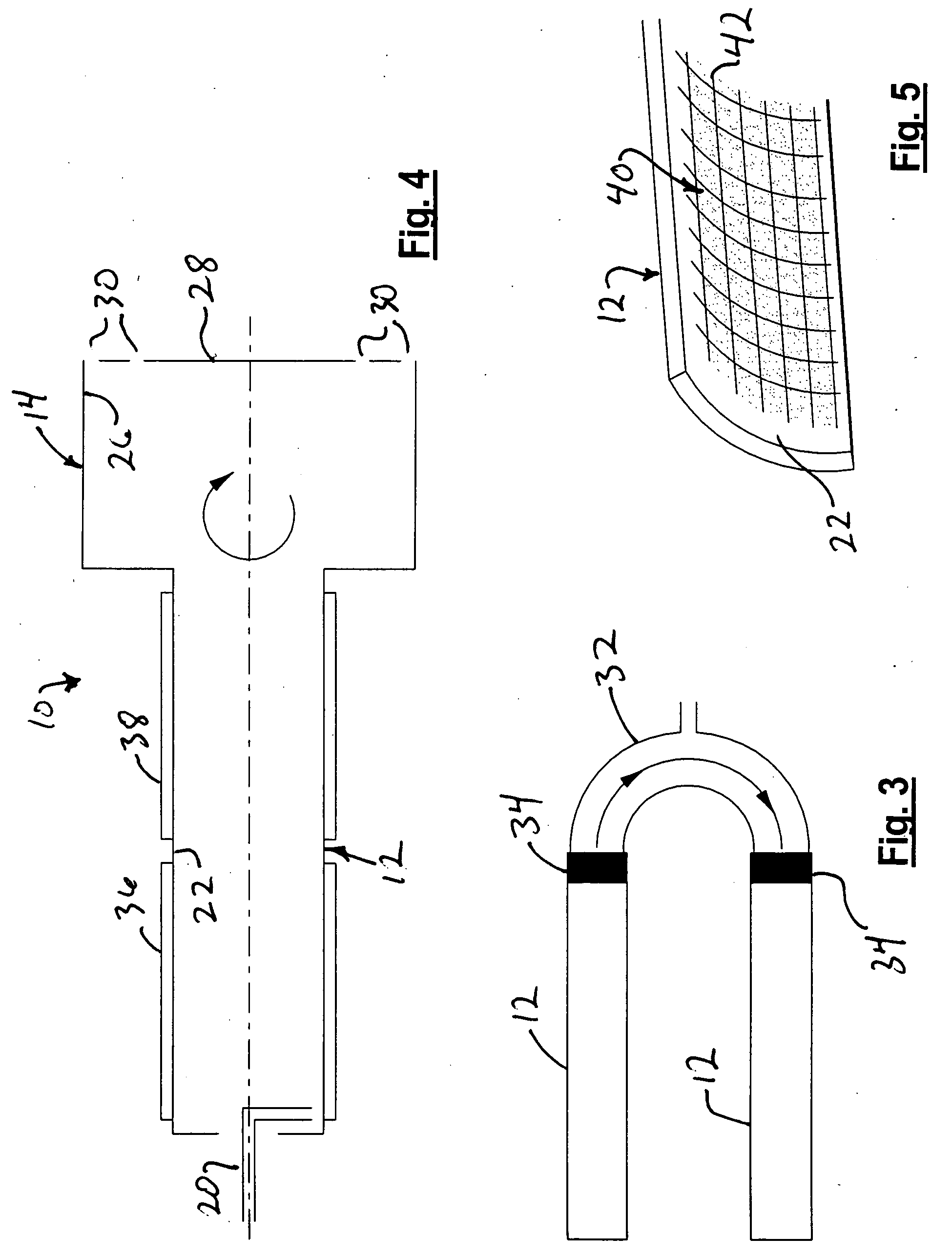
[0028] The primary tube 12 includes a feed tube 20 configured for depositing reactants onto an inner surface 22 of the primary tube 12. Alternatively, one or more feed tubes 20 configured in an array or coaxially as shown in FIG. 1B direct reactants toward a rotating mixing plate 24. The mixing plate 24 may be circular or any other shape. This adaptation allows rapid mixing of the reactant streams and is particularly suited for processes which require the mixing of reactants of different viscosities or the mixing of steams with vastly different flow rates. The centrifugal force then transfers the fluid from the mixing plate 24 to the inner wall 22. The surface of the mixing plate 24 may include structures to improve the hydrodynamics of the thin film on the surface. For example, a spiral structure on the surfa...


PUM


Abstract

The invention provides a thin film tube reactor, including an elongate tube that is rotatable about its longitudinal axis. A mixing plate rotatable about the tube's longitudinal axis may be positioned within the tube near the inlet. A plurality of fluid process components are fed into the tube and directed toward the mixing plate. In the absence of the mixing plate, the process components are directed toward the inner surface of the tube. Heating and cooling elements surround the tube to control the process temperature at particular points along the tube. A structured surface that is integral with or affixed to the inner surface of the tube immobilizes a catalyst slurry applied to the inner surface. A separation reservoir includes an end plate with a plurality of radially spaced outlet ports for controlling the output of the products from said separation reservoir.

Description

FIELD OF THE INVENTION [0001] This invention relates to chemical reactors and thermal processing equipment. BACKGROUND OF THE INVENTION [0002] A common problem in chemical reaction processes is how to achieve the proper hydrodynamics in the reactor to efficiently produce the desired products. The reactants must be mixed so that the molecules of the reaction components come into contact with the other components in the reaction including catalysts. The presence of a gaseous reactant requires the increase of the surface area of the boundary between the gas and the liquid components to increase the efficiency of the reaction. Many processes require fine temperature control or added energy from an electromagnetic field. In some cases rapid temperature changes are desired though difficult to achieve due to the thermal inertia of the reaction components. Also, it is often difficult to ensure proper saturation of the reaction components by an electromagnetic field as the outermost portion ...

Claims


Application Information

Patent Timeline
IPC IPC(8): B01J19/00B01J8/06
CPCB01F5/22B01J10/007B01J10/02B01J19/1887B01J19/1893B01J2219/00094B01J2219/00139B01J2219/182B01F25/74
Inventor LEVESON, PHILIP
Owner NANODYNAMICS INC
Why Eureka
Try Eureka