Al technical title is built by PatSnap Al team. It summarizes the technical point description of the patent document.
a coating fluid and pattern technology, applied in the direction of liquid/solution decomposition chemical coating, superimposed coating process, non-fibrous pulp addition, etc., can solve the problems of undue splitting, difficult to handle the coating material and form a uniform layer on the substrate, and the goal of asymmetrical coating
Inactive Publication Date: 2006-07-06
3M INNOVATIVE PROPERTIES CO
View PDF24 Cites 19 Cited by
Summary
Abstract
Description
Claims
Application Information
AI Technical Summary
This helps you quickly interpret patents by identifying the three key elements:
Problems solved by technology
Method used
Benefits of technology
[0004] The present invention is a method of defining a pattern of coating fluid on a surface which comprises introducing coating fluid containing microspheres onto a surface of an applicator roll. The topography of the applicator roll surface comprises at least one longitudinally extending circumferential, helical groove portion which is sized to at least partially receive the microspheres of the coating fluid therein, and at least one circumferential, longitudinally extending smooth surface portion. The method further comprises engaging the applicator roll surface with a doctor blade to remove coating fluid from the smooth surface portion thereof and to limit the amount of microspheres advanced past the doctor blade by the helical groove portion of the applicator roll surface, wherein a pattern of coating fluid containing microspheres remains on the applicator roll surface which is defined by the helical groove portion thereon and is formed to define at least one stripe of coating fluid containing microspheres.
Problems solved by technology
For example, if the microspheres are cut or sheared, the adhesive materials therein could start to agglomerate, thereby making it difficult to handle the coating material and form a uniform layer thereof on a substrate.
Such agglomeration also may cause the adhesive material to adhere to components of the coating equipment or further web processing equipment, thereby necessitating a shut down of the coating process while coating equipment and components are cleaned.
This goal has proved problematic in many processing conditions where metering and further processing of a microsphere adhesive based coating requires such activities as dispensing of the coating through a die under pressure, exposure of the coating to a doctor blade on a roller, or metering under pressure, exposure of the coating to a doctor blade on a roller, or metering of the coating by passing it through a nip between opposed rollers.
For instance, if there is insufficient space in a nip between opposed rolls for a microsphere to pass through that nip, it cannot do so.
The microspheres are then squeezed out to the sides of the roll and do not accumulate on any coating being deposited after the nip The deficiencies in prior art processes include inadequate transfer of adhesive from an etched gravure application roll to the web, or undue splitting of the coating material in film form during flexographic coating.
In addition, the shear sensitivity and / or poor rheological properties of the microsphere adhesive fluid may result in excessive coagulation (i.e., caused by agglomeration of sheared adhesive microspheres) and / or non-uniform coating lay down, which will result in non-uniform streaks of adhesive, mottled adhesive patterns, coating voids or an undesired “orange peel” coating effect which affect the adhesion level of the dried coating.
Method used
Image
Click on the blue label to locate the original text in one second.
Reading with bidirectional positioning of images and text.
Examples
Embodiment Construction
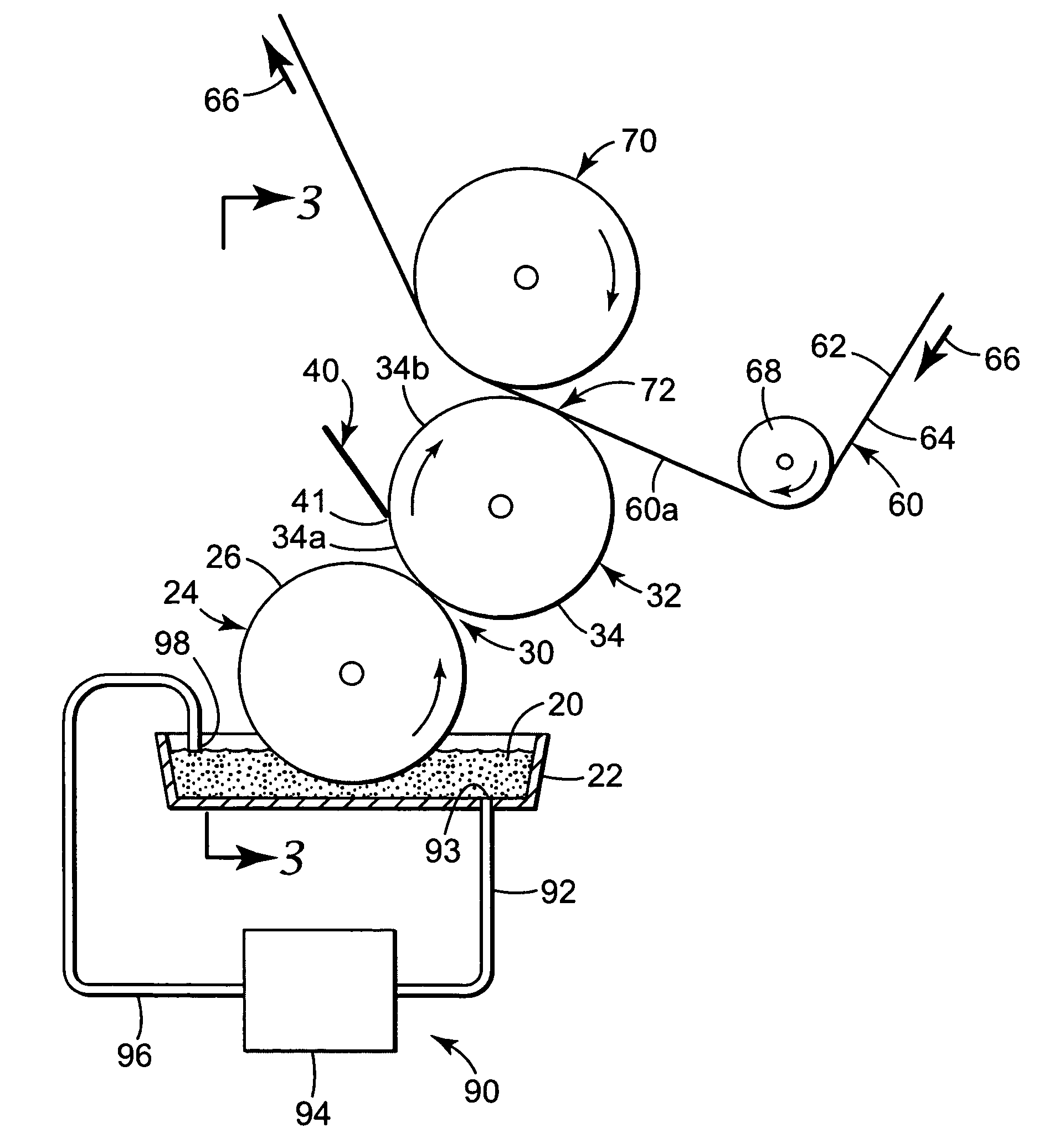
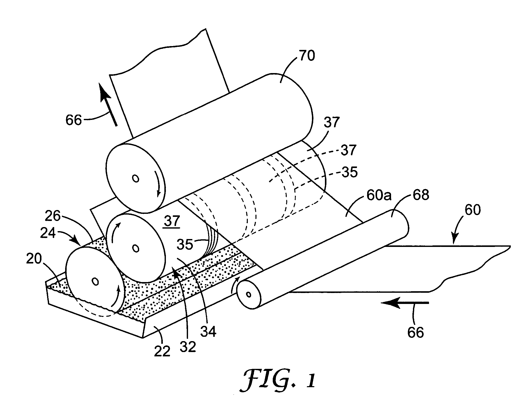
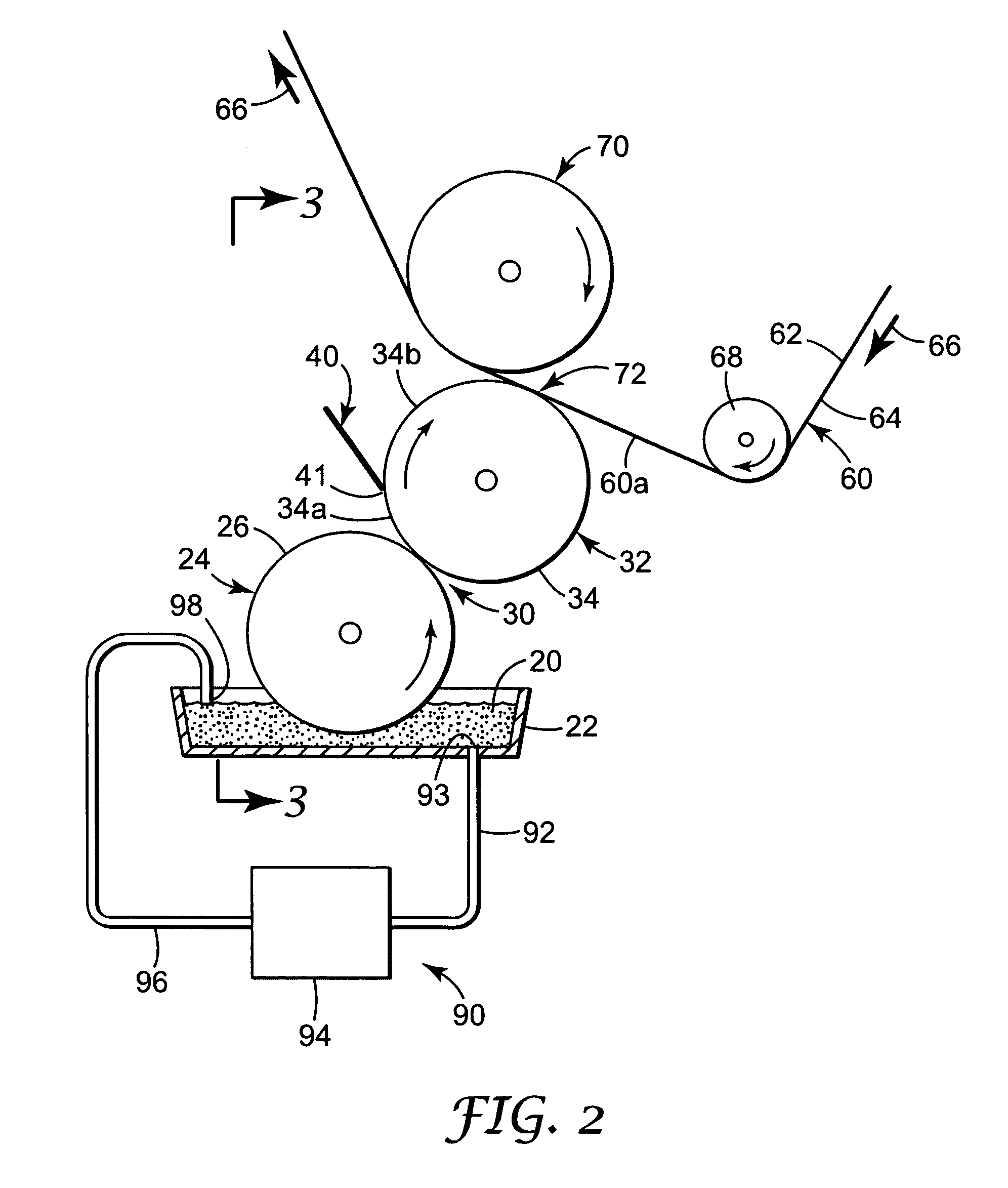
[0019] Applicants have discovered and developed a unique apparatus and process for selectively applying a down-web pattern of coating fluid onto a moving web. This pattern, in its simplest form, may comprise a single stripe of coating fluid deposited on the moving web or a plurality of parallel stripes applied along the length of the moving web. In addition, the pattern can be continuously applied to the moving web (i.e., a continuous stripe or plurality of stripes of coating fluid), or the application of the pattern can be stopped all together even though the web continues to move past the inventive coating apparatus. In addition, the apparatus can be configured to apply an intermittent pattern of coating fluid to the web (i.e., a discontinuous strip of coating fluid applied along the length of the moving web, such as “dashes” or blocks of coating fluid).
[0020] Alternative methods and apparatus for achieving these ends are disclosed herein. In each instance, the coating fluid is h...
PUM
Property
Measurement
Unit
angle
aaaaa
aaaaa
diameter
aaaaa
aaaaa
depth
aaaaa
aaaaa
Abstract
A method of defining a pattern of coating fluid on a surface includes introducing coating fluid containing microspheres onto a surface of an applicator roll, wherein the topography of the applicator roll surface comprises at least one longitudinally extending circumferential, helical groove portion which is sized to at least partially receive the microspheres of the coating fluid therein, and at least one circumferential, longitudinally extending smooth surface portion. The method further includes engaging the applicator roll surface with a doctor blade to remove coating fluid from the smooth surface portions thereof and to limit the amount of microspheres advanced past the doctor blade by the helical groove portion of the applicator roll surface. Thus, a pattern of coating fluid containing microspheres remains on the applicator roll surface which is defined by the helical groove portion thereon and is formed to define at least one stripe of coating fluid containing microspheres. The pattern of coating fluid is transferred from the applicator roll surface to a moving web by a reverse kiss coating.
Description
BACKGROUND OF THE INVENTION [0001] This application relates to a method for applying a coating fluid. More particularly, the present invention relates to applying coating fluid in a specifically desired longitudinally disposed pattern. [0002] In various product designs, it is desirable to coat one or more stripes of a coating material in a down-web or cross web pattern on a substrate such as a moving paper web or polymeric film web. In some applications, the coating material comprises a pressure sensitive adhesive (either permanent or removable). In particular, such adhesives may constitute pressure sensitive adhesive coatings including microsphere based adhesives, such as those disclosed in U.S. Pat. Nos. 6,296,932, 5,824,748, 5,756,625, 5,714,237, 5,571,617, 5,045,569, 4,495,318, 4,166,152, 3,857,731, and 3,691,140. It is important when processing such microsphere based adhesives that the relatively delicate microspheres themselves not be damaged or ruptured. For example, if the m...
Claims
Application Information
Patent Timeline
Application Date:The date an application was filed.
Publication Date:The date a patent or application was officially published.
First Publication Date:The earliest publication date of a patent with the same application number.
Issue Date:Publication date of the patent grant document.
PCT Entry Date:The Entry date of PCT National Phase.
Estimated Expiry Date:The statutory expiry date of a patent right according to the Patent Law, and it is the longest term of protection that the patent right can achieve without the termination of the patent right due to other reasons(Term extension factor has been taken into account ).
Invalid Date:Actual expiry date is based on effective date or publication date of legal transaction data of invalid patent.
Patent Type & Authority Applications(United States)