Alcohol beverage dispensing apparatus

a technology for dispensing equipment and alcohol beverages, which is applied in the field of cooling systems, can solve problems such as preventing proper dispensing of beer, and achieve the effect of reducing manufacturing costs

Inactive Publication Date: 2006-07-13
ANHEUSER BUSCH INBEV SA
View PDF12 Cites 27 Cited by
  • Summary
  • Abstract
  • Description
  • Claims
  • Application Information

AI Technical Summary

Benefits of technology

[0019] An advantage of the present invention is that forming the keg from two identical shells provides a manufacturing cost reduction.
[0020] Preferably, the end wall portion of each half shell is formed with a raised annular collar and a face plate extending across the collar to normally close the collar. The face plate of one of the two keg half shells is adapted to engage a cooling plate of a dispensing apparatus in heat transfer relation therewith and the other of the two keg half shells is at least partially removed to form an aperture for receiving a valve and spear for filling into and dispensing from the keg the beverage. This preferred construction of the keg renders the keg operable for use in a home beverage dispensing system such as, for example, a beer dispensing apparatus.
[0021

Problems solved by technology

Further, due to limited countertop space requirements, there still is a need to chill or cool the beer in the dispensing apparatus to serving temperatures in an optimal manner in spite of the limited space.
However, in the event the keg is left in the disp

Method used


Image

  • Alcohol beverage dispensing apparatus
  • Alcohol beverage dispensing apparatus
  • Alcohol beverage dispensing apparatus

Examples


Embodiment Construction

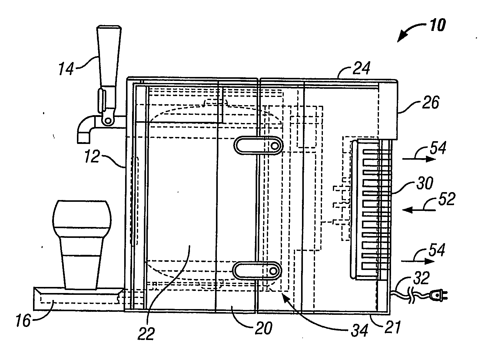
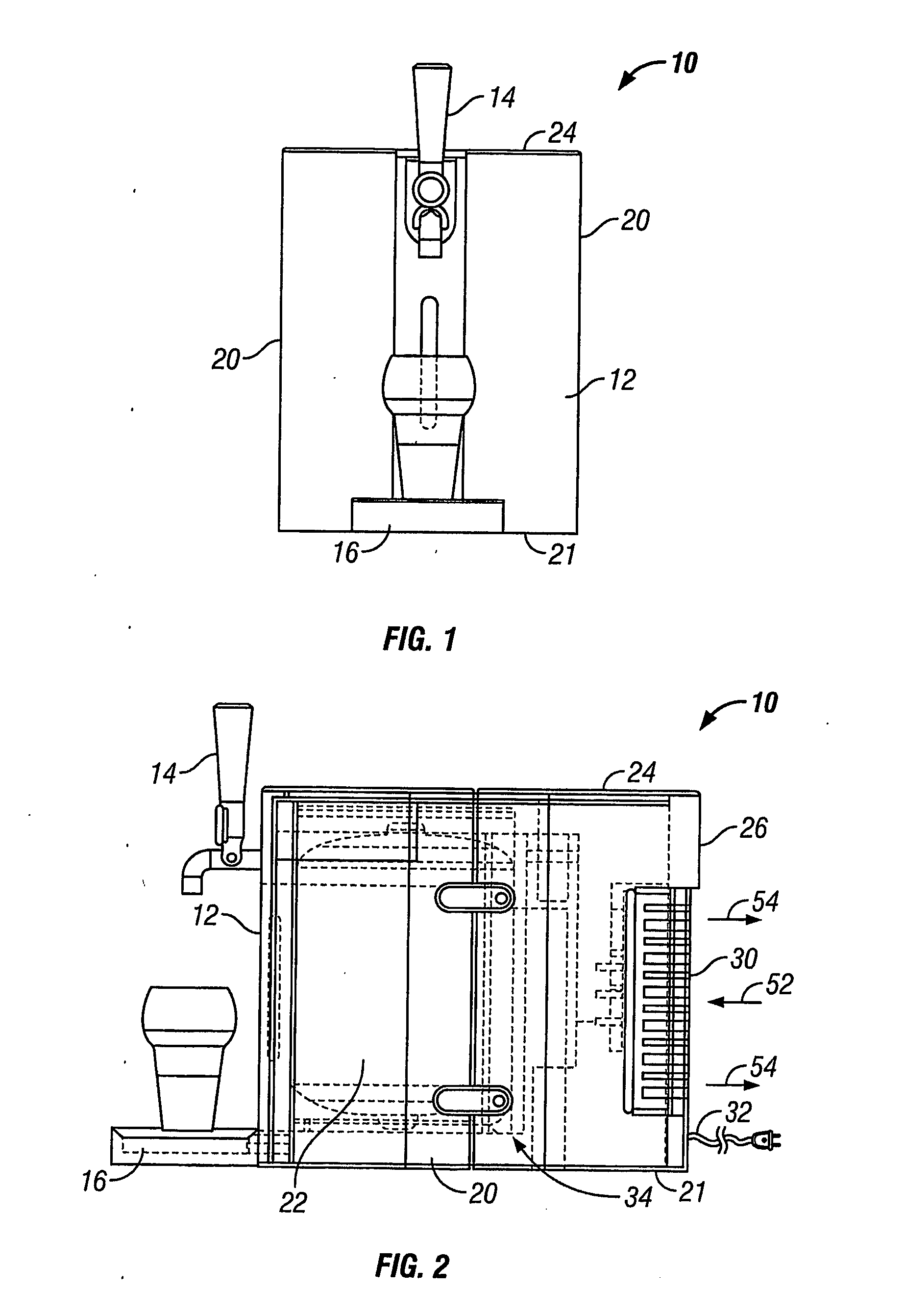
[0034] Referring to FIGS. 1 and 2 there is shown a home beer dispensing apparatus, appliance or unit 10. The dispensing apparatus 10 is primarily intended for use in domestic kitchens but may also be used in utility rooms, garages, domestic bars, caravans etc. While the preferred embodiment relates to dispensing beer, alternatively carbonated solutions or other alcohol beverages may be dispensed by apparatus 10.

[0035] The home beer dispensing apparatus 10 has a front wall 12 and a dispensing tap 14 protruding forward of the front wall 12. A drip tray 16 also protrudes forward of the front wall 12 and is adapted to support an open glass container 18 below the dispensing tap 14. The home beer dispensing apparatus 10 further has a base 21 adapted to rest on a counter top. The front wall 12 is an extension of two pivoting side walls 20 which may be moved between closed and open positions to allow the keg 22 (see FIG. 2 in broken lines) to be inserted into the housing of the home beer d...


PUM


Abstract

A cooling system for a home beer dispensing apparatus has a mediated thermal bridge providing a bank of latent cooling capacity. The bridge may have a cavity filled with a cooling solution with at least one series of spaced apart heat exchange fins extending substantially along and interstitially into the cavity from at least one wall of the cavity so as to enhance heat transfer across the cavity. The bridge is arranged in thermal conducting relation through a cooling plate between a keg containing the beer and a Peltier thermoelectric cooling device adapted to cool the cooling solution by extracting heat therefrom to an active heat sink. A fan directs air flow horizontally along the fins of the sink and out the two lateral open sides of the heat sink. This prevents heat from rising in the apparatus and thereby affecting other system component parts. The cooling solution may comprise 5% by volume glycol and freezes at a temperature below that of water providing an improved thermal bank. The cooling plate has an electrical resistance heater mounted therein to maintain the temperature of beer in the keg adjacent a bottom portion thereof above the freezing temperature of the beer. The cooling system is economical in its space requirements and enhances the chilling of the beer to a desired serving temperature. The invention also provides a beer keg for such systems.

Description

FIELD OF THE INVENTION [0001] The present invention relates to a cooling system for use in an alcohol beverage dispensing apparatus and in particular, relates to a cooling system having a mediated thermal bridge for use in a home beer dispensing apparatus. It further relates to the construction of a container, namely a beer keg, for use in such systems. BACKGROUND OF THE INVENTION [0002] Beer dispensing apparatus are known in the art for dispensing of draft beer in taverns and the like. Typically, the beer is chilled prior to being dispensed by passing through a conical run of tube that passes through a chilled compartment containing ice and water. In some instances the compartment is refrigerated. Such draft beer dispensers are utilized in taverns where the large volumes of beer are dispensed everyday and the taverns have room to store such chillers. This is not the case for a domestic or home beer dispensing apparatus that is adapted to sit on a countertop in a kitchen where space...

Claims


Application Information

Patent Timeline
IPC IPC(8): F25B21/02B67D1/04B67D1/08F25D31/00
CPCB67D1/0462B67D1/0869F25B21/02F25D31/006F25D2331/802F25D2331/806
Inventor WAUTERS, ALBERTDONKER, HANSANDERSON, IANHALKET, ANDREW R.BFRASER, CHRISTINEA
Owner ANHEUSER BUSCH INBEV SA
Why Eureka
Try Eureka