Vehicular transmissions utilizing slipper ring clutch control

a technology of clutch control and slipper ring, which is applied in the direction of mechanical actuated clutches, mechanical apparatus, gearing, etc., can solve the problems of ineffective operation of internal combustion engines and engine rotation speed, and achieve the effects of reducing packaging footprint, reducing torque loss, and reducing part cos

Inactive Publication Date: 2006-07-13
GM GLOBAL TECH OPERATIONS LLC
View PDF8 Cites 16 Cited by
  • Summary
  • Abstract
  • Description
  • Claims
  • Application Information

AI Technical Summary

Benefits of technology

[0010] By employing selectively engageable slipper ring clutch mechanisms within vehicular transmission combinations, many benefits may be garnered. These benefits may include, reduced part cost, smaller packaging footprint, lower torque loss, reduced control scheme complexity, increased power density, and the ability to shift gears in both a synchronous and non-synchronous state.

Problems solved by technology

All internal combustion engines have a maximum engine rotational speed above which the internal combustion engine can not effectively operate due to limitations of various internal combustion engine components, such as the valvetrain or reciprocating components.

Method used


Image

  • Vehicular transmissions utilizing slipper ring clutch control
  • Vehicular transmissions utilizing slipper ring clutch control
  • Vehicular transmissions utilizing slipper ring clutch control

Examples


Embodiment Construction

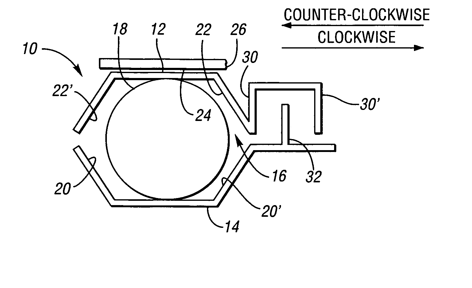
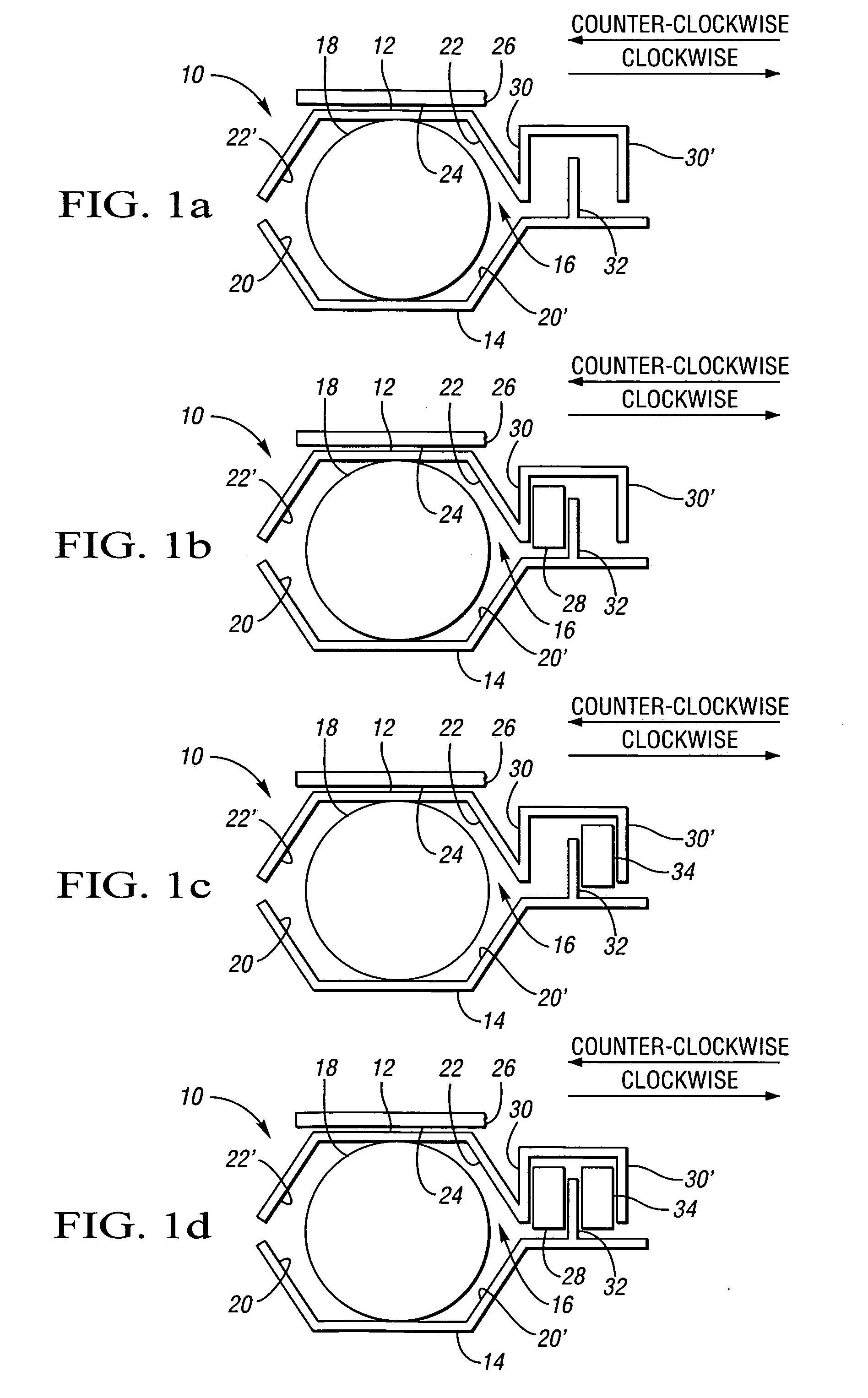
[0024] Referring to the figures wherein like reference numbers refer to like or similar components, FIGS. 1a, 1b, 1c, and 1d are schematic diagrams of a selectively engageable slipper ring clutch 10 each illustrating one of four states of engagement. The outer slipper ring 12 and the inner slipper ring 14 of the slipper ring clutch 10 define a cavity 16 with a roller element 18 disposed therein. The outer slipper ring 12 is of a split ring design, described hereinafter, allowing the outer slipper ring 12 to expand radially outward. FIG. 1a represents a state in which the slipper ring clutch 10 is locked or engaged in both rotational directions, clockwise and counter-clockwise. With clockwise rotation of the inner slipper ring 14, the roller element 18 will engage ramp 20 of the inner slipper ring 14. Subsequently, the roller element 18 will engage ramp 22 of the outer slipper ring 12. This engagement of ramp 22 will force the outer slipper ring 12 to expand outward and frictionally ...


PUM


Abstract

Provided are various vehicular transmission combinations utilizing selectively engageable spiral-type couplings or slipper ring clutches, operable to provide smooth shifting between gear sets, in place of traditional shifting mechanisms, such as hydraulic plate-type clutches, or synchronizers.

Description

CROSS REFERENCE TO RELATED APPLICATION [0001] This application claims the benefit of U.S. Provisional Application No. 60 / 642,390, filed Jan. 7, 2005, which is hereby incorporated by reference in its entirety.TECHNICAL FIELD [0002] The present invention relates to vehicular transmissions and, more particularly, to the use of slipper ring clutch mechanisms to control various types of vehicular transmissions. BACKGROUND OF THE INVENTION [0003] Automobiles require shiftable transmissions as a result of the physics of the internal combustion engine. All internal combustion engines have a maximum engine rotational speed above which the internal combustion engine can not effectively operate due to limitations of various internal combustion engine components, such as the valvetrain or reciprocating components. Additionally, internal combustion engines have an engine speed range where horsepower and torque are at their maximum. The transmission, through changes in gear ratio, allows the rati...

Claims


Application Information

Patent Timeline
Patent Type & Authority Applications(United States)
IPC IPC(8): F16H3/08
CPCF16D23/04F16D41/088Y10T74/19233F16H3/44Y10T74/19284F16H3/006
Inventor MAGUIRE, JOEL M.WITTKOPP, SCOTT H.
Owner GM GLOBAL TECH OPERATIONS LLC
Why Eureka
Try Eureka