
Method and System of Conserving Plasma Torch Consumable

a technology of consumables and plasma torch, which is applied in the field of plasma cutting systems, can solve the problems of affecting the wear resistance of inserts, and still being susceptible to wear, so as to reduce the wear resistance of consumable components and reduce the wear resistance of components

Active Publication Date: 2006-07-13
ILLINOIS TOOL WORKS INC
View PDF13 Cites 64 Cited by
  • Summary
  • Abstract
  • Description
  • Claims
  • Application Information

AI Technical Summary

Benefits of technology

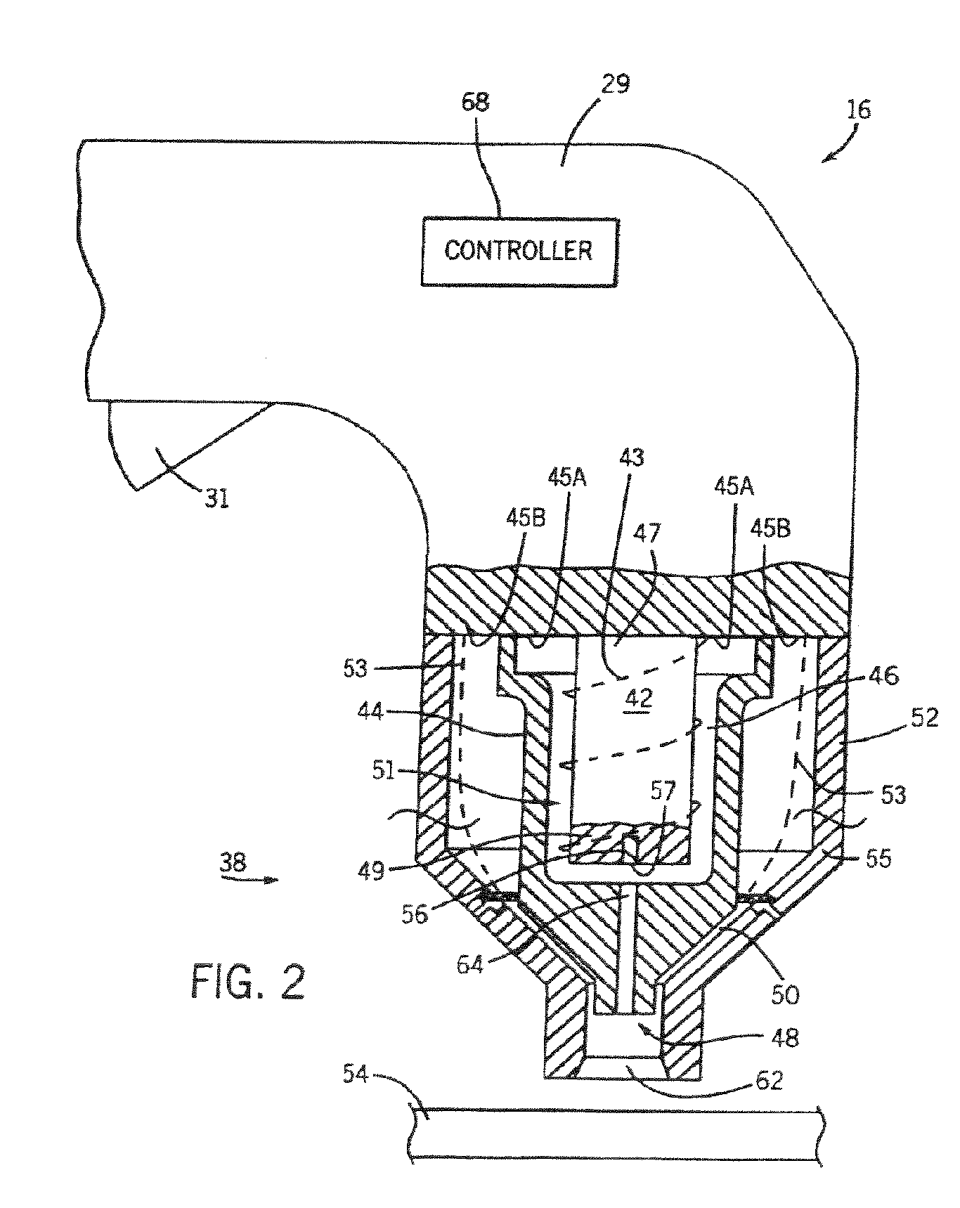
[0008] The present invention provides a system and controller that overcomes the aforementioned drawbacks. The controller is configured to control a plasma cutting system to reduce the wear of the consumable components of the plasma torch. The controller, during a single trigger activation, maintains a delay between the collapse of an arc and the generation of a subsequent arc. Such a control allows the components of the consumable assembly to cool thereby reducing wear of the components associated with generation of the subsequent arc.

Problems solved by technology

Although the insert is better equipped to support the plasma arc than the body of the electrode, it is still susceptible to wear.
Moving the contacts of the plasma torch from a separated or operating position to a contacting idle position results in an impact between the parts as they engage one another.
This impact dislodges a portion of the liquefied material of the insert and expedites wear of the insert.
Upon completion of a cutting process, when the cutting arc collapses, the flow of gas through the plasma torch is also disrupted.
This pressure differential within the torch also detrimentally affects retention of the liquefied portion of the insert.
That is, the relatively sudden pressure change effectively sucks or blows a portion of the liquefied material from the insert.
The sudden pressure change and the mechanical movement of the components of the plasma torch, individually and in combination, shorten the life cycle of the insert by removing that portion of the insert liquefied during a cutting process.
Such operation increases consumable component consumption resulting in increased cost and decreased operational efficiency.

Method used


Image

  • Method and System of Conserving Plasma Torch Consumable
  • Method and System of Conserving Plasma Torch Consumable
  • Method and System of Conserving Plasma Torch Consumable

Examples


Embodiment Construction

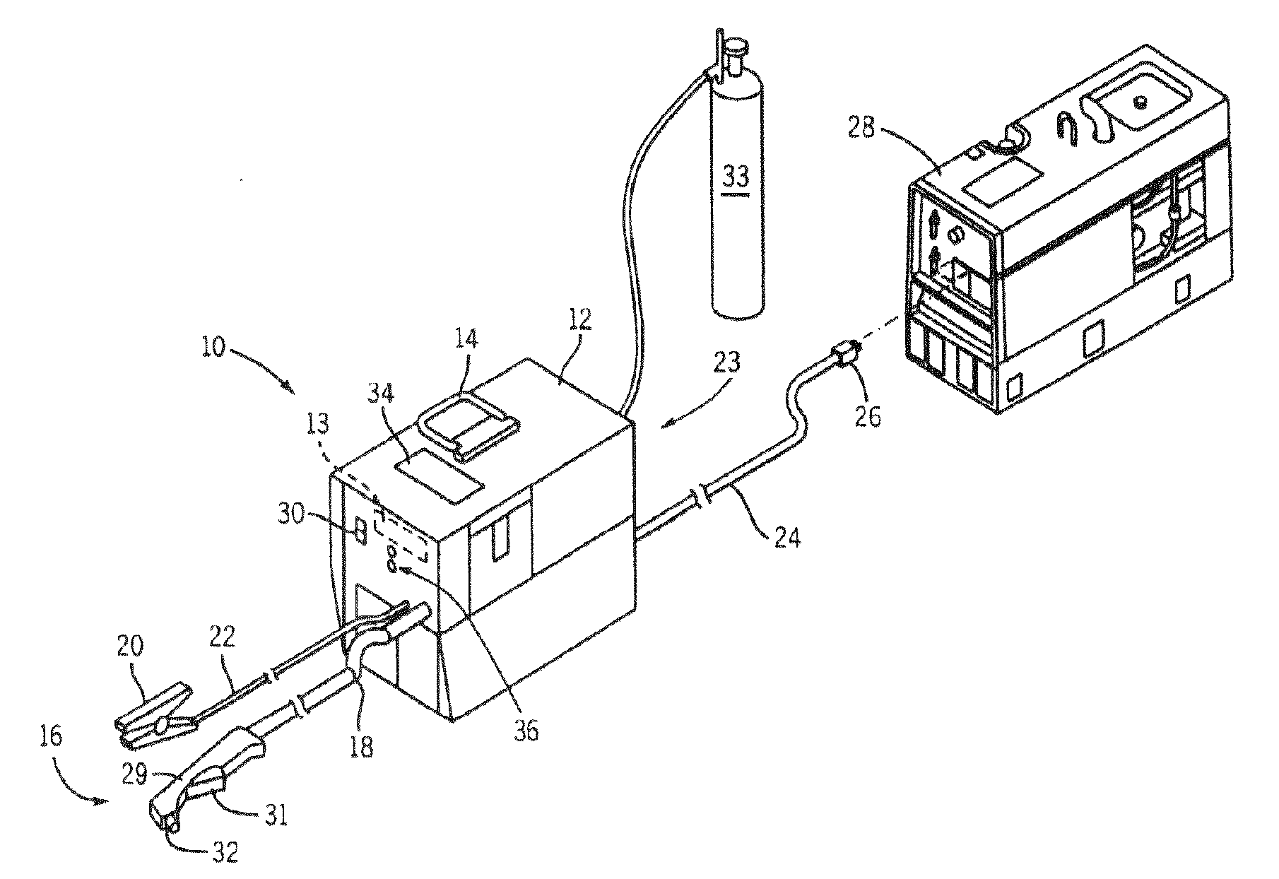
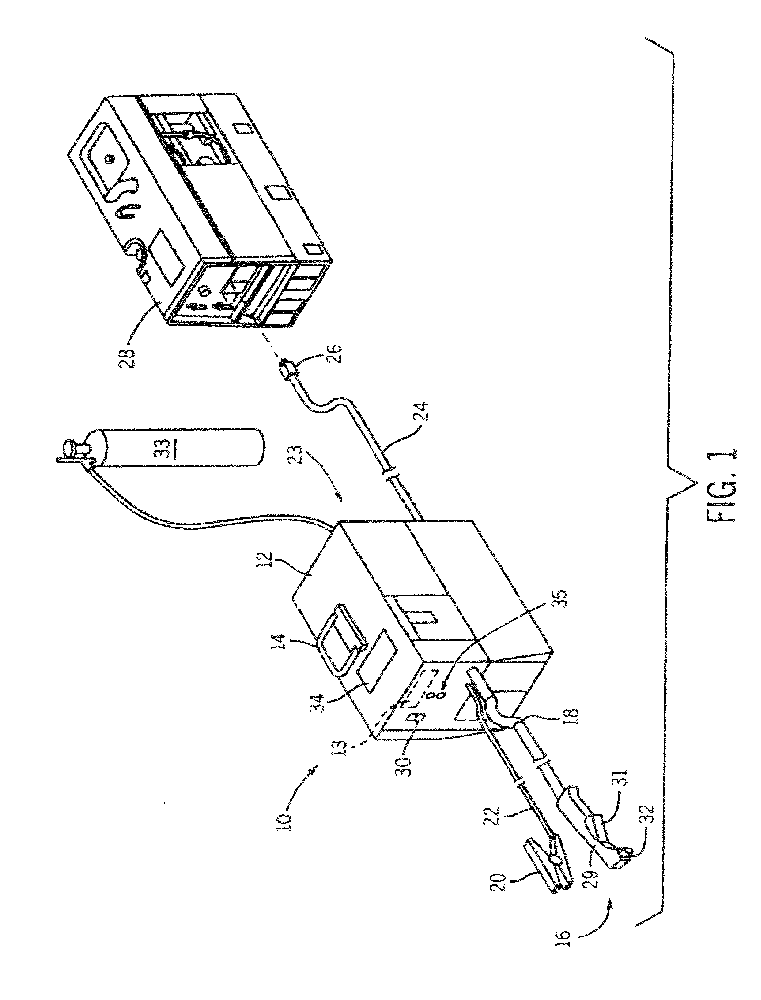
[0018]FIG. 1 shows a plasma cutting system 10 according to the present invention. Plasma cutting system 10 is a high voltage system with open circuit output voltages that typically range from approximately 230 Volts Direct Current (VDC) to over 300 VDC. Plasma cutting system 10 includes a power source 12 to condition raw power and generate a power signal suitable for plasma cutting applications. Power source 12 includes a processor 13 that receives operational feedback and monitors the operation of a plasma cutting system 10. Power source 12 includes a handle 14 to effectuate transportation from one site to another. Connected to power source 12 is a torch 16 via a cable 18. Cable 18 provides torch 16 with power and compressed air or gas, and also serves as a communications link between torch 16 and power source 12. Torch 16 includes a handle portion 29, or torch body, having a trigger 31 thereon and work tip 32 extending therefrom. Although shown as attached to torch 16, it understo...


PUM

PropertyMeasurementUnit
voltagesaaaaaaaaaa
cutting timeaaaaaaaaaa
timeaaaaaaaaaa

Abstract

A system for conserving a consumable component of a plasma torch is disclosed. The system includes a controller of a plasma torch that is connected to a power source. The controller is configured to, during a single trigger actuation, delay generation of an arc after a prior arc collapses. Such a control allows the consumable components of the plasma torch to cool prior to subsequent operation.

Description

BACKGROUND OF THE INVENTION [0001] The present invention relates generally to plasma cutting systems and, more particularly, to a controller for use with such systems. [0002] Plasma cutting is a process in which an electric arc is used for cutting a workpiece. Plasma cutters typically include a power source, an air supply, and a torch. The torch, or plasma torch, is used to create and maintain the plasma arc that performs the cutting. A plasma cutting power source receives an input voltage from a transmission power receptacle or generator and provides output power to a pair of output terminals, one of which is connected to an electrode and the other of which is connected to the workpiece. An air supply is used with most plasma cutters to carry and propel the arc to the workpiece and help cool the torch. [0003] There are multiple ways of initiating this cutting process, for example contact starting or high frequency or high voltage starting. Generally, in contact start plasma cutters...

Claims


Application Information

Patent Timeline
Patent Type & Authority Applications(United States)
IPC IPC(8): B23K9/00B23K9/02
CPCB23K10/00B23K10/006H05H1/36
Inventor SCHNEIDER, JOSEPH C.
Owner ILLINOIS TOOL WORKS INC
Learn More