Welding method, welding system and welding jig

Inactive Publication Date: 2006-07-13
HONDA MOTOR CO LTD
View PDF4 Cites 5 Cited by
  • Summary
  • Abstract
  • Description
  • Claims
  • Application Information

AI Technical Summary

Benefits of technology

[0007] The present invention has been made in view of the above problems. It is an object of the present invention to provide a welding method, a welding system, and a welding jig for reducing the effect of thermal strain caused by welding when a fuel tank for a motorcycle is welded, thereby preventing the fuel tank from cracking.

Problems solved by technology

Furthermore, since the center of gravity of the fuel tank is displaced upwardly by the height of the flanges 206, the flanges 206 are disadvantageous with respect to efforts to lower the center of gravity of the motorcycle.
According to this proposal, however, useless space is present above the flanges, which limits the capacity of the fuel tank.
If the fuel tank is automatically welded by a robot, then since the fuel tank must be firmly secured in place, the fuel tank tends to crack since thermal strains cannot be relieved during welding, resulting in a reduced yield.
In such a case, when the fuel tank cracks, it still needs to be repaired by a skilled welding operator.

Method used


Image

  • Welding method, welding system and welding jig
  • Welding method, welding system and welding jig
  • Welding method, welding system and welding jig

Examples


Embodiment Construction

[0038] An embodiment of the present invention will be described below with reference to FIGS. 1 through 14. A welding method, a welding system 10, and a welding jig 10a according to the embodiment serve to weld a fuel tank 12 for a motorcycle.

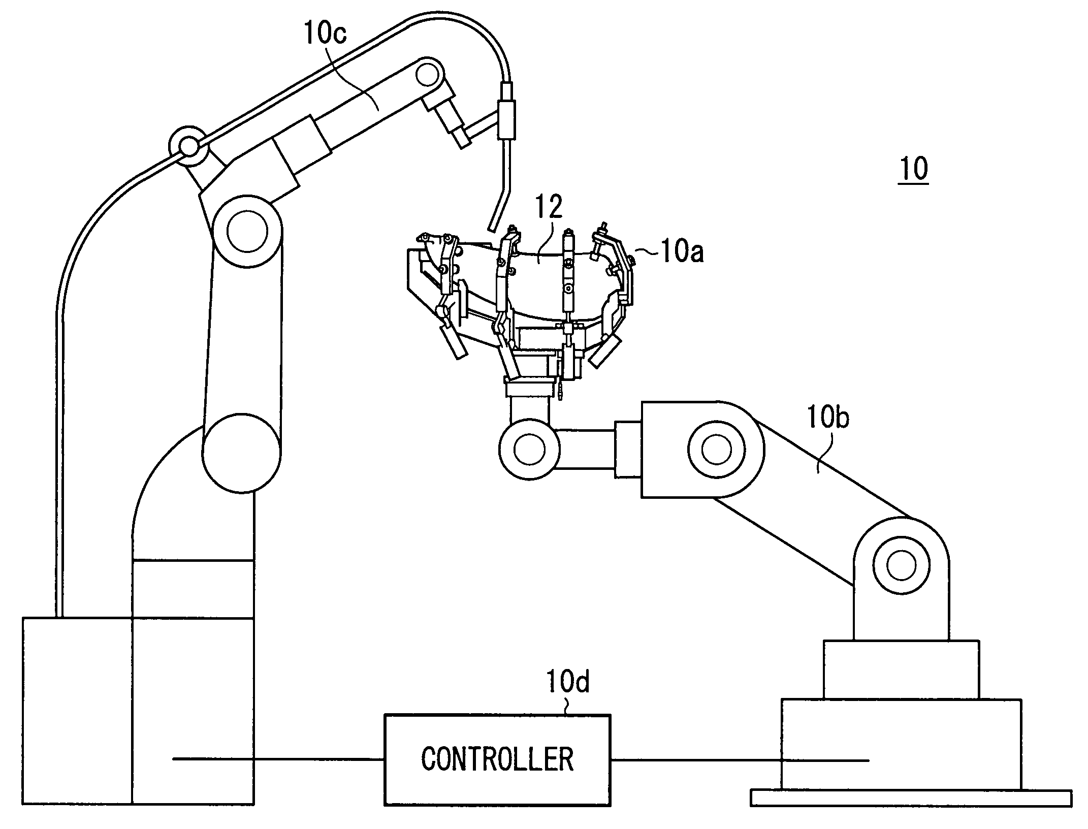
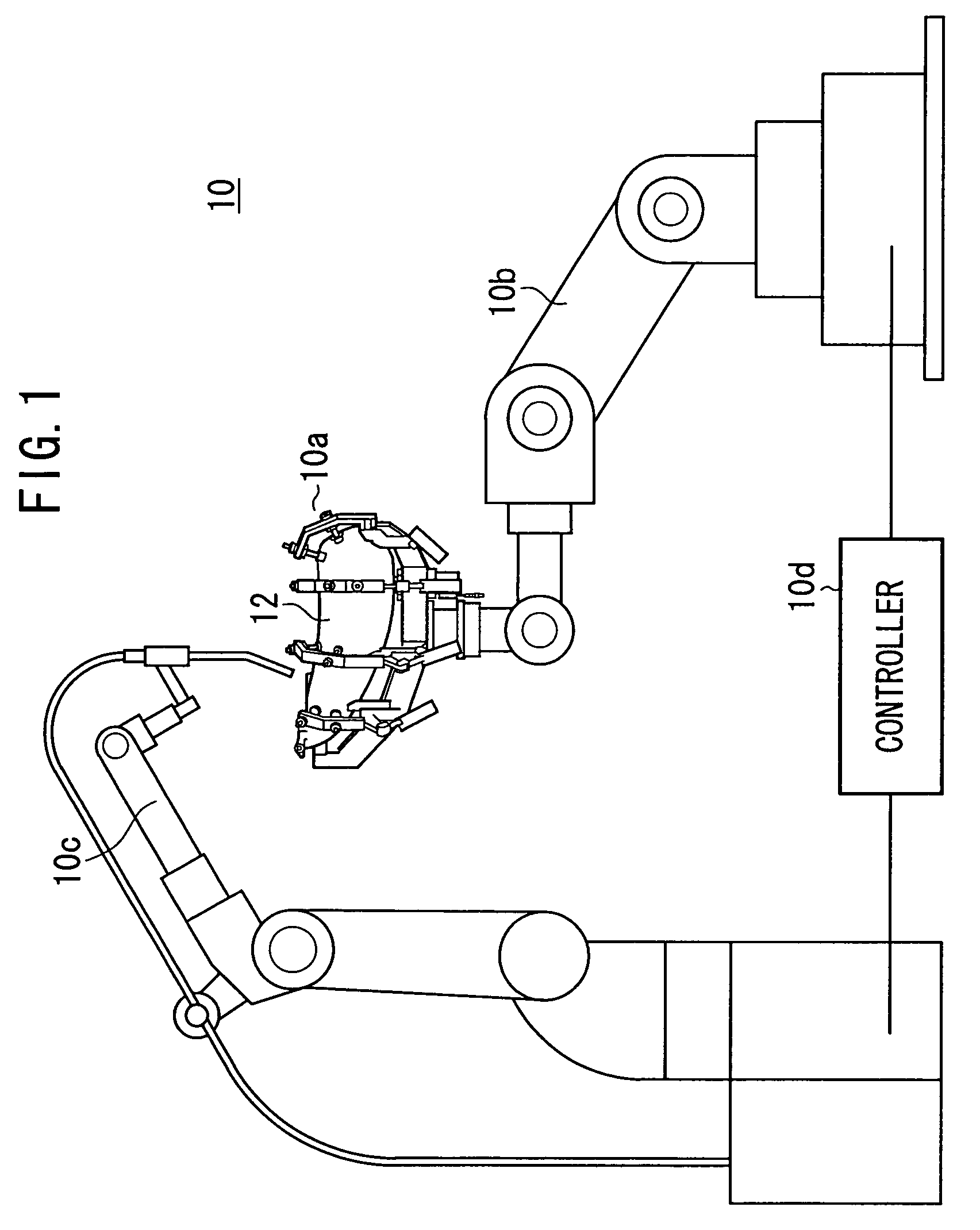
[0039] As shown in FIG. 1, the welding system 10 has a welding jig 10a (see FIG. 2) for holding the fuel tank 12, a jig robot 10b for setting the fuel tank 12 held by the welding jig 10a at a predetermined position, a welding robot (welding machine) 10c for performing a welding process, and a controller 10d. The controller 10d is connected to cylinders 28 (see FIG. 2) of the welding jig 10a, a positioning mechanism 44 (see FIG. 7), the jig robot 10b, and the welding robot 10c, for controlling the welding system 10 in its entirety.

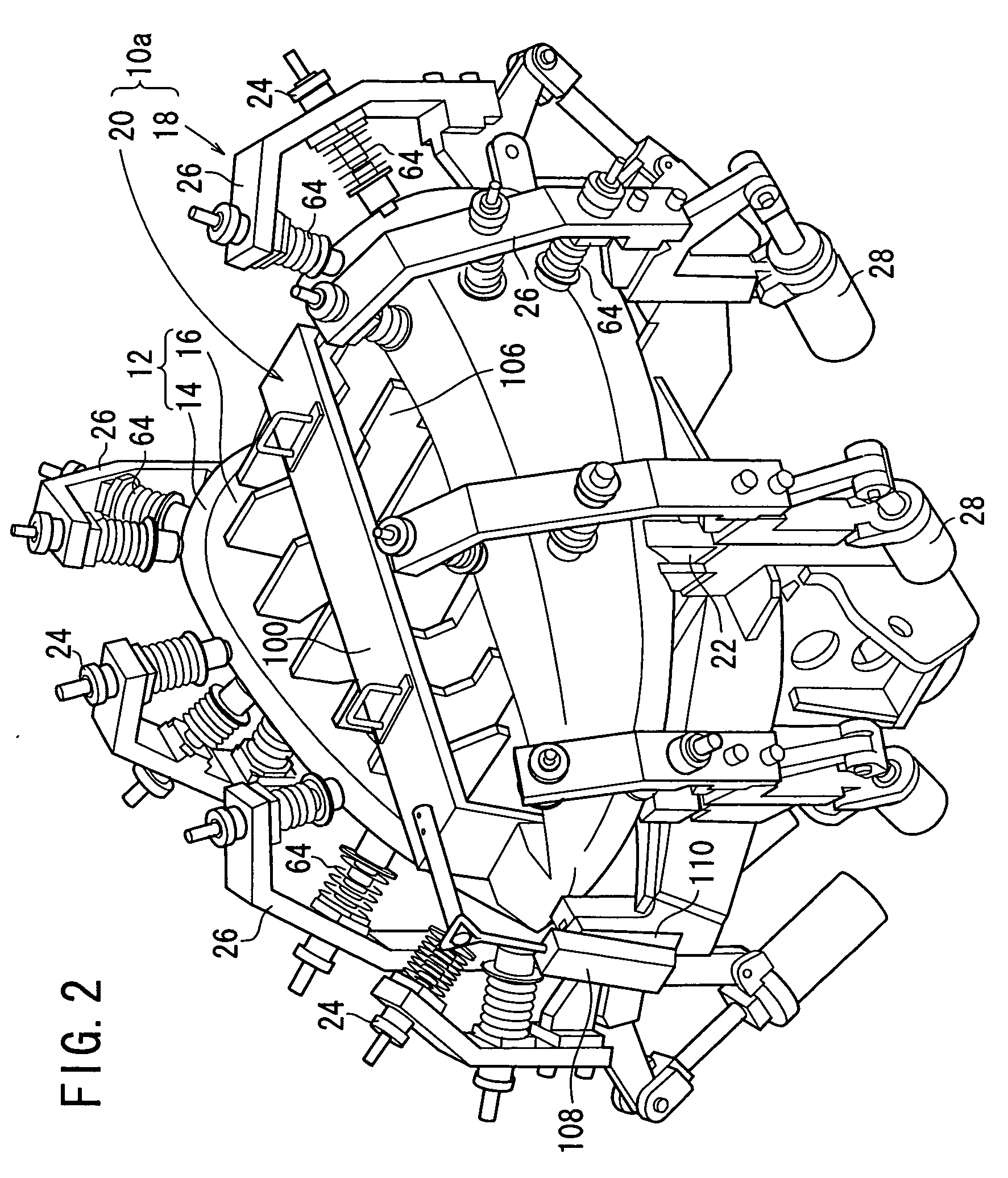
[0040] As shown in FIG. 2, the welding jig 10a is a jig for fixing an outer side panel 14 and an inner side panel 16 of the motorcycle fuel tank 12 when the outer side panel 14 and the inner side panel 16 are welded ...


PUM

PropertyMeasurementUnit
Lengthaaaaaaaaaa
Forceaaaaaaaaaa
Resilienceaaaaaaaaaa

Abstract

A plurality of attachments having springs hold the outer plate of a fuel tank, and an inner jig positions the inner plate. The attachments are attached to clamp arms which are opened / closed by cylinders. When the overlap portion between the outer and inner plates is welded, the thermal deformation caused by welding is accommodated by the springs. The attachments are spaced from the fuel tank in the order in which the welding point is approached.

Description

TECHNICAL FIELD [0001] The present invention,relates to a welding method, a welding system, and a welding jig for welding a fuel tank for a motorcycle, and more particularly to a welding method, a welding system, and a welding jig for reducing the effect of thermal strain caused by welding. BACKGROUND ART [0002] As shown in FIG. 15 of the accompanying drawings, a fuel tank 200 for a motorcycle generally has an outer side panel 202 and an inner side panel 204 having its bottom welded to the outer side panel 202. The outer side panel 202 and the inner side panel 204 have respective ends bent downwardly into flanges 206 that are generally seam-welded. [0003] In motorcycles, a motorcycle having a steering handle at a high position, and which is operated by a rider whose upper half body is kept substantially upright, i.e., a so-called American-type motorcycle, has its fuel tank 200 regarded as being particularly important in terms of appearance. For the fuel tank 200 to be aesthetically ...

Claims


Application Information

Patent Timeline
IPC IPC(8): B23K37/00B23K37/04B62J35/00
CPCB23K9/0026B23K37/0435B23K37/0443B23K2201/006B62J35/00B23K2101/006
Inventor YAMAOKA, NAOJIIWAGUCHI, YOSHIMASASHIMADA, TAKASHIARAI, SETSUOISHII, TOSHIO
Owner HONDA MOTOR CO LTD
Why Eureka
Try Eureka