Cleaning of submerged surfaces by discharge of pressurized cavitating fluids

a cavitating fluid and submerged surface technology, applied in the direction of cleaning using liquids, combustion types, vessel construction, etc., can solve the problems of serious development, no implementation in practice, and devices that require serious development and new design, so as to increase fuel consumption, increase hydrodynamic drag, and deterioration of operational specifications

Inactive Publication Date: 2006-07-13
PIVOVAROV ALEXANDER
View PDF15 Cites 24 Cited by
  • Summary
  • Abstract
  • Description
  • Claims
  • Application Information

AI Technical Summary

Benefits of technology

[0015] Portions of sea going vessels that are disposed below the waterline, such as the hull surfaces, screw-steering groups, sea chest screens and boxes, are prone to paint peeling, corrosion, and overgrowth of animal and plant organisms. As a result, the vessel experiences increased hydrodynamic drag that results in deterioration of operational specifications and inefficient fuel consumption. It is known that the accumulation of biological growth on a vessels hull of a mere 1 millimeter can increase fuel consumption by approximately one percent (1.0%). It has further been found that the hull of a vessel may accumulate biological growth of approximately in the northern seas 3-5 kg/sq.m and more than 50 kg/sq.m in tropical seas with biological growth reaching up to 20.0 cm. By way of example, an ocean going tanker of 270 tones displacement traversing between the Persian Gulf and Europe may suffer continuous decreases in speed from 17 knots to 14 knots after two years of operation without cleaning. As a direct result, the power plant must operate at higher power thereby substantially increasing fuel consumption.
[0016] Losses realized by the owner of a vessel after operating for 2 years without biological growth cleaning, assuming a fuel price of $470.00 U.S. per ton are as follows:
[0017] Ocean-going freighters are normally cleaned in dry docks. However, dry dock cleaning is expensive and thus must usually be deferred and coordinated with other schedu...

Problems solved by technology

Inspite of advantages of implementation of those inventions, those devices required serious development and new design.
Those inventions are very specific and because of lot disadvantages, have no implementation in practice.
Those devices are in very good efficiency, but they are still have to be serious developed.
The two specifically referenced devices of the prior art, however, are each burdended with similar disadvantages.
More particularly, both the hand-held and wheeled devices are limited to discharging cavitating water flow, and are not adapted for the additional discharge of a an abrasive material, such as sand, for more effective removal of debris and marine growth from submerged surfaces.
In addition, each of the specifically referenced devices include control levers that have proven difficult to manipulate by an operator in a diving suit.
Portions of sea going vessels that are disposed below the waterline, such as the hull surfaces, screw-steering groups, sea chest screens and boxes, are prone to paint peeling, corrosion, and overgrowth of animal and plant organisms.
As a result, the vessel experiences increased hydrodynamic drag that results in deterioration of operational specifications and inefficient fuel consumption.
As a direct result, the power plant must operate at higher power thereby substantially increasing fuel consumption.
However, dry dock cleaning is expensive and thus must usually be deferred and coordinated with other scheduled repair works.
The regular cleaning of portions of the hull below the water line of a tanker of 50 thousand tons displacement during the interdock period after one year of its operation saves 950 tons of diesel, i.e. up to $446,500 U.S. An overgrowth of animal and plant organisms on hydraulic structures may further degrade operation of those structures.
For example, such overgrowth has a negative impact on heat exchanger efficiency, th...

Method used


Image

  • Cleaning of submerged surfaces by discharge of pressurized cavitating fluids
  • Cleaning of submerged surfaces by discharge of pressurized cavitating fluids
  • Cleaning of submerged surfaces by discharge of pressurized cavitating fluids

Examples


Embodiment Construction

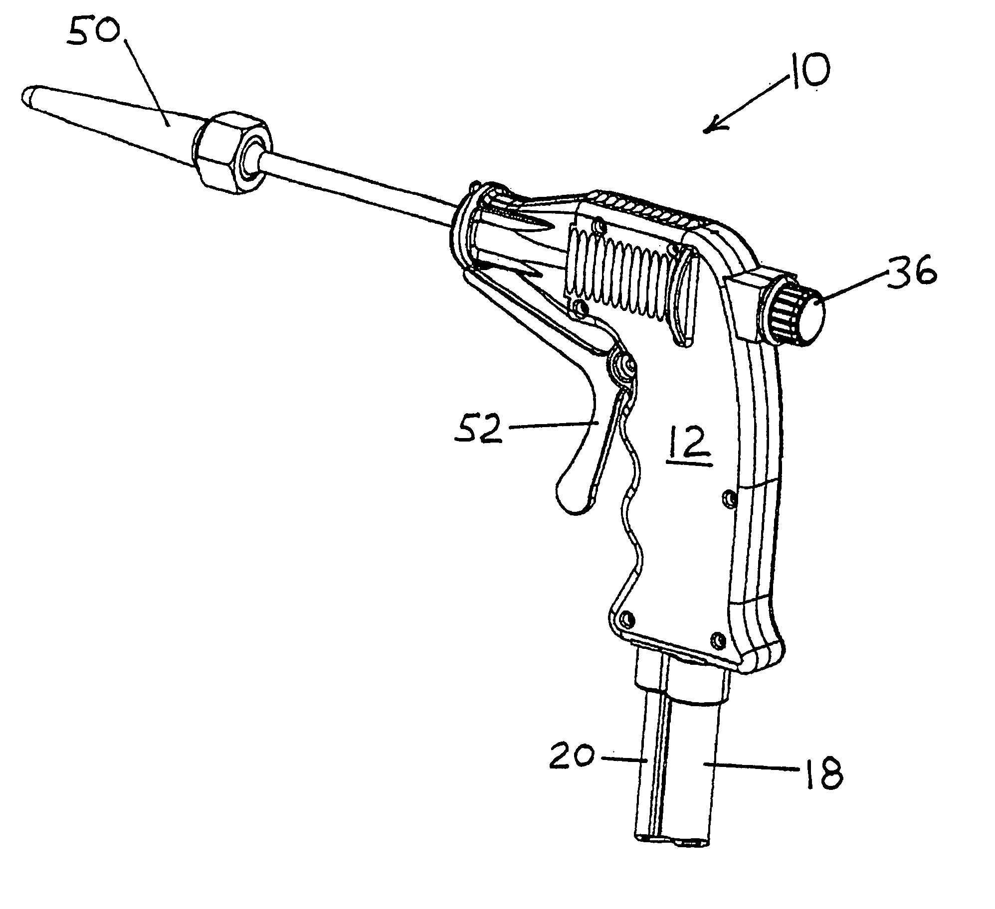
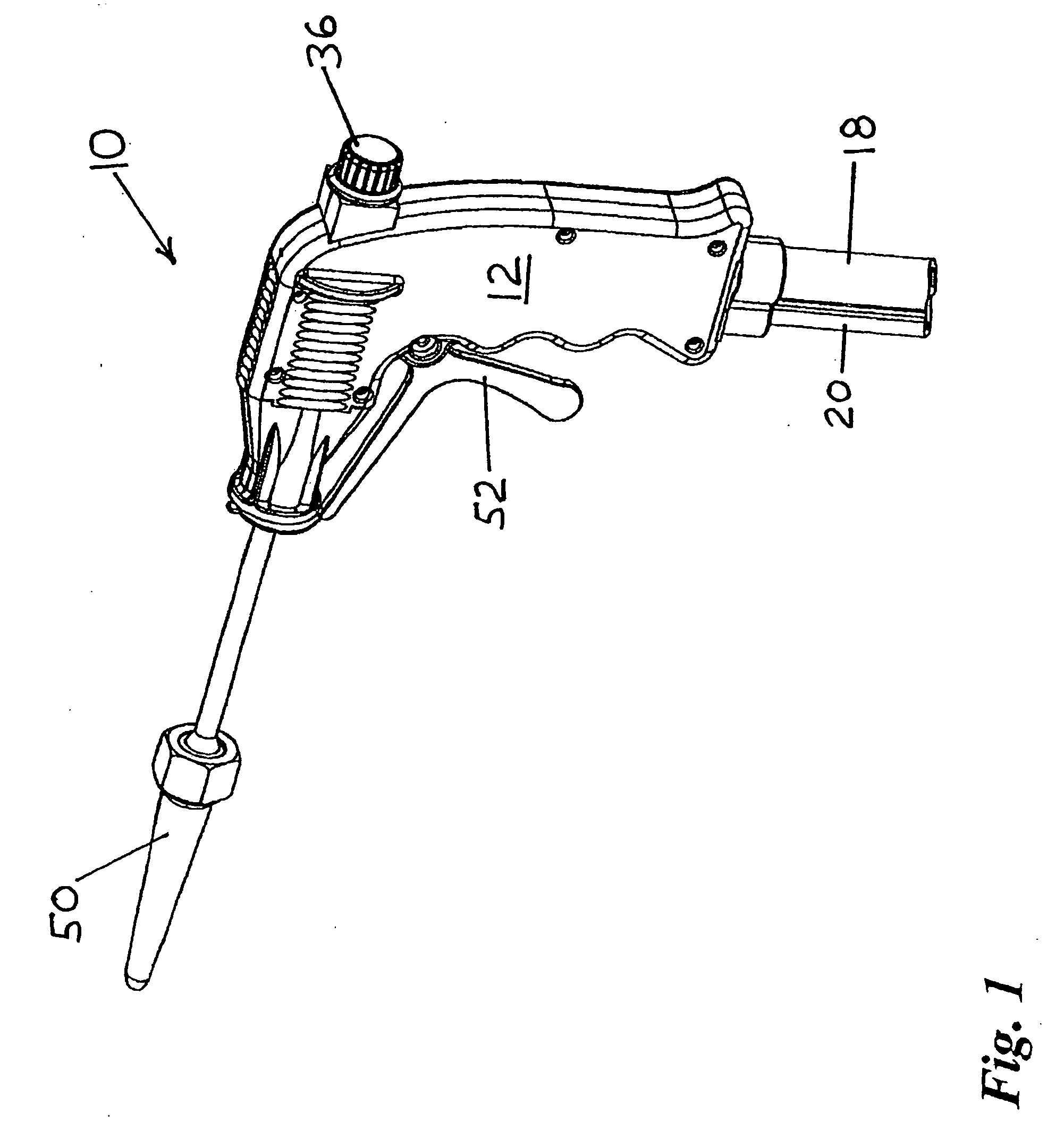
[0074]FIG. 1 depicts hand-held hydrodynamic tools for use in removing debris from submerged surfaces using cavitating streams of pressurized fluid in accordance with the prior art. There is depicted a fluid discharge apparatus, generally referenced as 10, suitable for use in pressure cleaning. Fluid discharge apparatus 10 is adapted to commingle two fluids, preferably a pressurized liquid and a pressurized gas, and to discharge the commingle fluids in a high-pressure stream wherein the gas is disposed in the center of a stream of swirling liquid. As discussed more fully below, the pressurized stream is particularly useful in removing deposits from surfaces, and particularly useful in removing marine deposits from submerged surfaces.

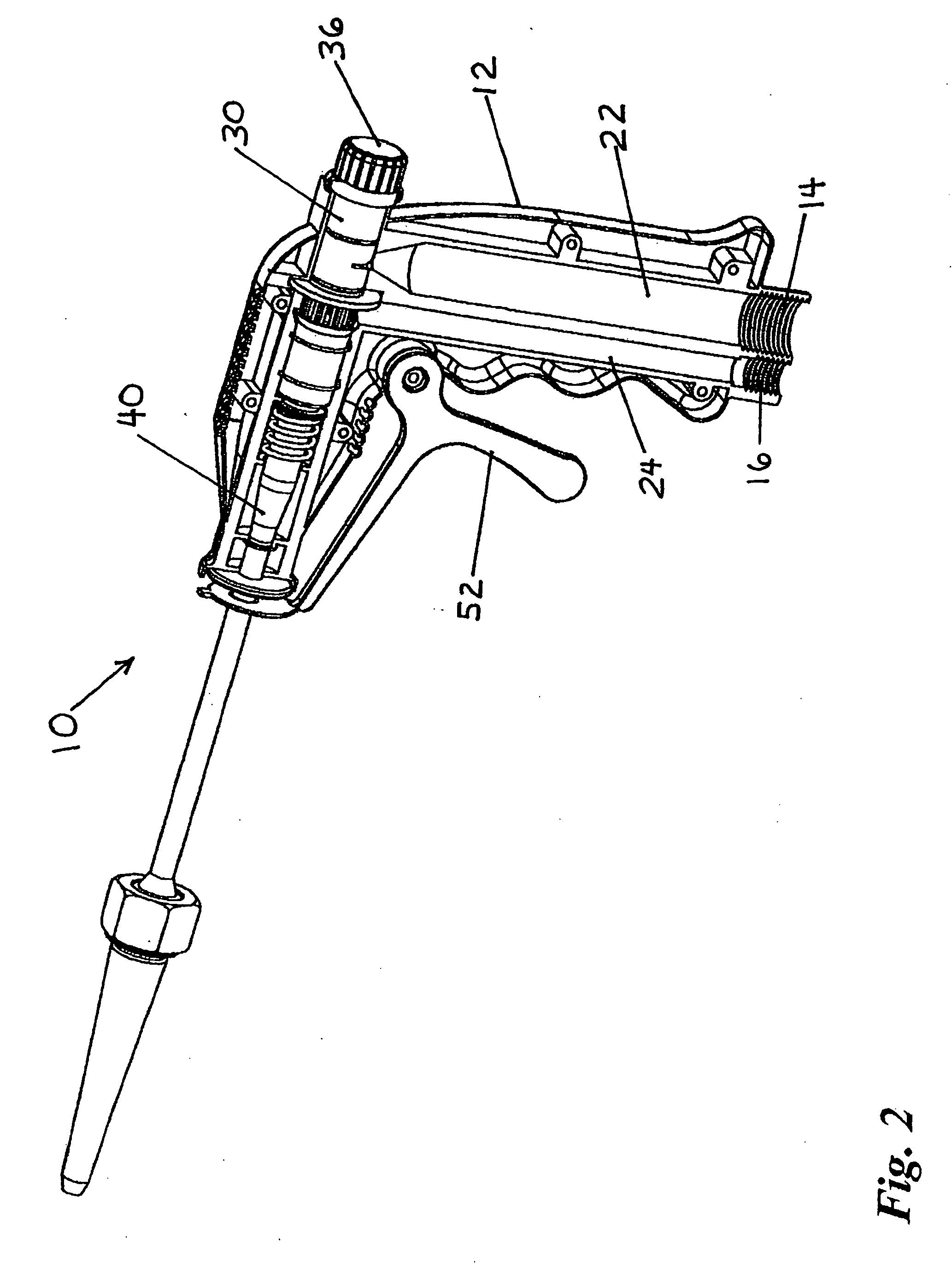
[0075] As best depicted in FIGS. 1-7, fluid discharge apparatus 10 includes a pistol grip shaped housing 12 having a handle adapted with internally threaded ports, referenced as 14 and 16, for receiving first and second pressurized fluids via inlet hoses...


PUM


Abstract

A fluid discharge apparatus adapted to discharge a cavitating stream of pressurized liquid along with the selective discharge of a secondary material, such as an abrasive, for removing dirt, debris, barnacles, marine growth, and other substances from submerged surfaces is provided. More particularly, the invention contemplates a introducing a pressurized liquid into a cavitation generating chamber to create and discharge a cavitating stream, and a secondary inlet for injecting abrasive material, such as silica, into the chamber to improve cleaning effectiveness. The gas bubbles within the cavitating liquid stream that essentially explode upon impacting debris resulting in tremendous pressure fluxuations provides improved effectiveness in removing debris and aquatic growth from the submerged surface. The combination of a secondary substance, such as an abrasive material, foam, or compressed gas enhances cleaning effectiveness. The invention further improves upon the control of such devices with controls, such as a pistol grip or rotational grip controllers, that allow the diver/operator to adjust flow rates and thrust without releasing his grasp. An improved hand-held apparatus is disclosed with a pistol grip and trigger actuator, and an improved wheeled vehicle is disclosed with improved control handles adapted to actuate valves and closure ports.

Description

CROSS REFERENCE TO RELATED APPLICATIONS [0001] This application is a continuation-in-part of U.S. patent application Ser. No. 11 / 071,143, filed on Mar. 3, 2005, which is a continuation in part of U.S. patent application Ser. No. 10 / 926,440, filed on Aug. 25, 2004, which is a continuation-in-part of U.S. patent application Ser. No. 10 / 396,981, filed Mar. 25, 2003.STATEMENT REGARDING FEDERALLY SPONSORED RESEARCH OR DEVELOPMENT [0002] N / A COPYRIGHT NOTICE [0003] A portion of the disclosure of this patent document contains material that is subject to copyright protection. The copyright owner has no objection to the facsimile reproduction by anyone of the patent document or patent disclosure as it appears in the Patent and Trademark Office patent file or records, but otherwise reserves all copyrights. BACKGROUND OF THE INVENTION [0004] 1. Field of the Invention [0005] The present invention relates generally to fluid discharging apparatus, and, more particularly, to an apparatus and metho...

Claims


Application Information

Patent Timeline
IPC IPC(8): B05B9/01F02M61/00A62C31/02B05B7/02B05B1/34B05B7/04B05B7/10B05B7/12B05B12/00B63B59/08
CPCA62C31/03B05B1/341B05B7/0416B05B7/10B05B7/12B05B12/002B08B3/026B63B59/08B05B17/06
Inventor PIVOVAROV, ALEXANDER
Owner PIVOVAROV ALEXANDER
Why Eureka
Try Eureka