Method and apparatus for wind turbine air gap control

a technology of wind turbines and air gaps, applied in the control of electric generators, mechanical equipment, machines/engines, etc., can solve the problems of economic prohibitive use, reduced air gap distance, non-uniformity, etc., and achieve uniform air gap

Inactive Publication Date: 2006-07-13
GENERAL ELECTRIC CO
View PDF5 Cites 129 Cited by
  • Summary
  • Abstract
  • Description
  • Claims
  • Application Information

AI Technical Summary

Benefits of technology

[0006] In another embodiment, a wind turbine generator is provided. The wind turbine generator including a stator having a core and a plurality of stator windings circumferentially spaced about a generator longitudinal axis, and a rotor rotatable about the generator longitudinal axis, wherein the rotor includes a plurality of magnetic elements coupled to a radially outer periphery of the rotor such that an airgap is defined between the stator windings and the magnetic element

Problems solved by technology

Such loads are channeled from the rotor to the wind turbine base through the bearing and may tend to deflect structural components of the rotor in the load path such that the airgap distance is reduced and/or made non-uniform.
However, the size and weight di

Method used


Image

  • Method and apparatus for wind turbine air gap control
  • Method and apparatus for wind turbine air gap control
  • Method and apparatus for wind turbine air gap control

Examples


Embodiment Construction

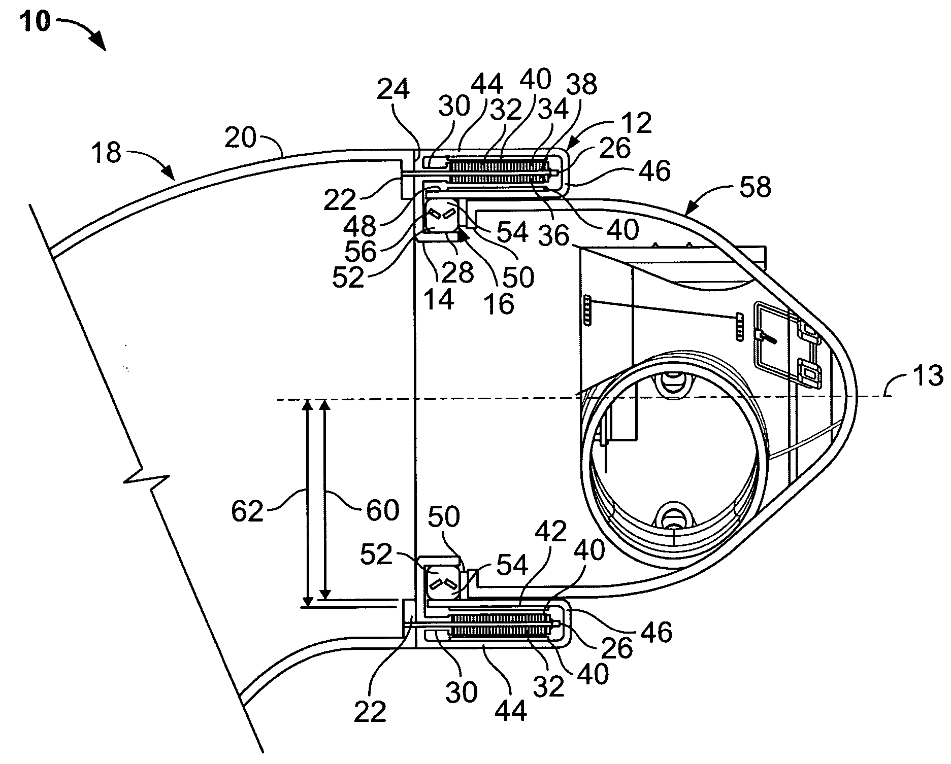
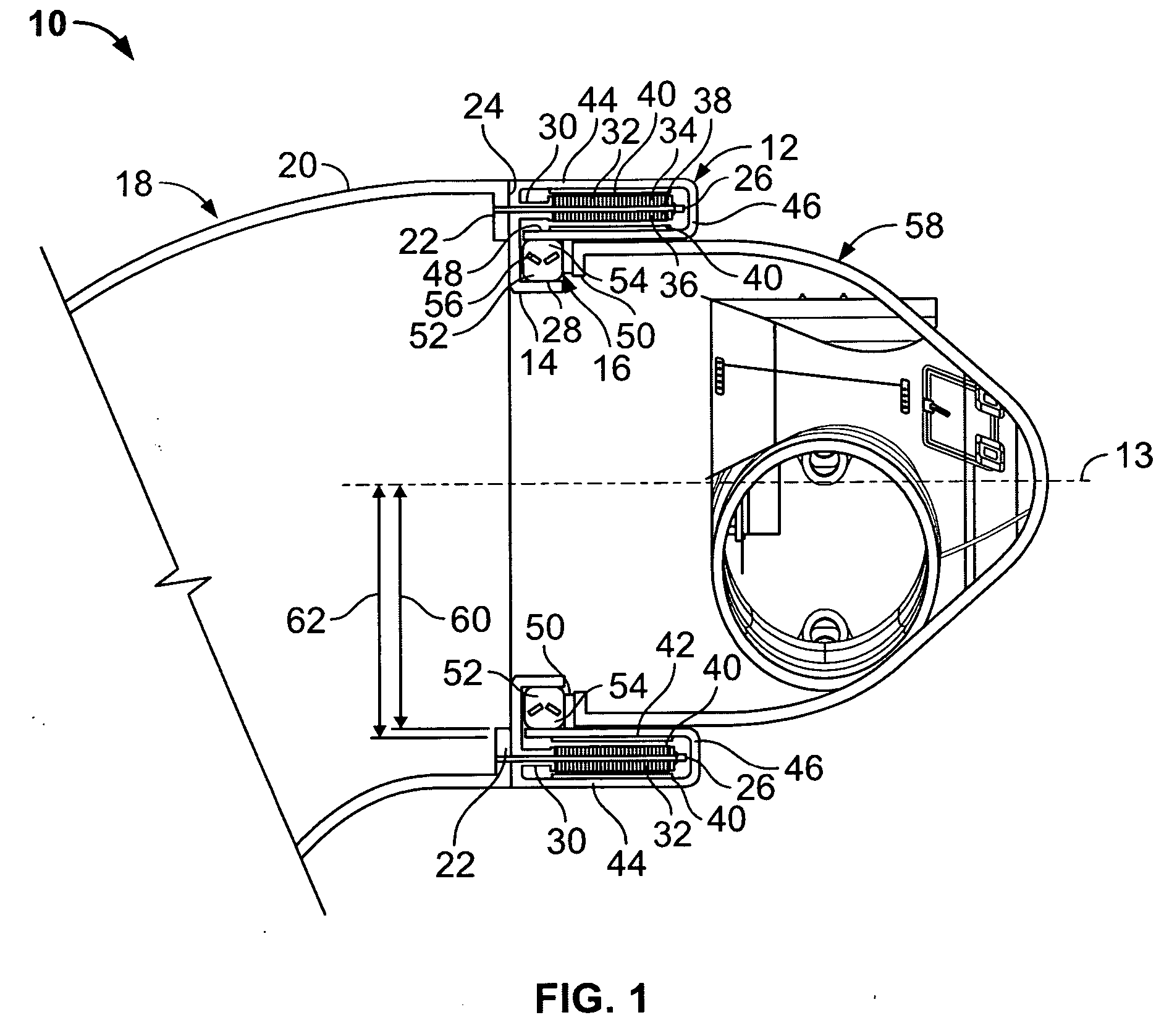
[0014]FIG. 1 is a schematic elevation illustration of an exemplary wind turbine generator 10 that includes a rotor 12, a stator 14 and a bearing 16. In the exemplary embodiment, a base 18 couples to a tower (not shown). Base 18 includes a body 20 and a base flange 22. Stator 14 is configured to couple to base flange 22 through face to face engagement of base flange 22 and a complementary stator flange 24. In the exemplary embodiment, stator 14 is fastened to mating flange 22 through a plurality of bolts 26 spaced circumferentially about a longitudinal axis 13 of generator 10. In an alternative embodiment, stator 14 is fastened to base flange 22 using weldment and / or other fasteners. Stator 14 includes a radially inner bearing support 28 extending axially from stator flange 24. Stator 14 also includes a core mount rim 30 that extends axially from stator flange 24. In the exemplary embodiment, a stator core 32 is coupled to core mount rim 30 using bolts 26. Stator core 32 includes at ...


PUM


Abstract

Methods and apparatus for assembling a wind turbine generator are provided. The wind turbine generator includes a core and a plurality of stator windings circumferentially spaced about a generator longitudinal axis, a rotor rotatable about the generator longitudinal axis wherein the rotor includes a plurality of magnetic elements coupled to a radially outer periphery of the rotor such that an airgap is defined between the stator windings and the magnetic elements and the plurality of magnetic elements including a radially inner periphery having a first diameter. The wind turbine generator also includes a bearing including a first member in rotatable engagement with a radially inner second member, the first member including a radially outer periphery, a diameter of the radially outer periphery of the first member being substantially equal to the first diameter, the rotor coupled to the stator through the bearing such that a substantially uniform airgap is maintained.

Description

BACKGROUND OF THE INVENTION [0001] This invention relates generally to electric generators, and more particularly, to methods and apparatus for controlling an air gap between a rotor and a stator in a wind-powered turbine generator. [0002] Recently, wind turbines have received increased attention as an environmentally safe and relatively inexpensive alternative energy source. With this growing interest, considerable efforts have been made to develop wind turbines that are reliable and efficient. [0003] Generally, a wind turbine includes a plurality of blades coupled to a rotor through a hub. The rotor is mounted within a housing or nacelle, which is positioned on top of a tubular tower or base. Utility grade wind turbines (i.e., wind turbines designed to provide electrical power to a utility grid) can have large rotors (e.g., 30 or more meters in diameter). Blades on these rotors transform wind energy into a rotational torque or force that drives the rotor of one or more generators,...

Claims


Application Information

Patent Timeline
IPC IPC(8): F03D9/00H02P9/04
CPCF03D9/002F03D11/0008F05B2220/7066Y02E10/722Y02E10/725H02K7/1838F03D80/70F03D9/25F03D15/20Y02E10/72
Inventor GRANT, JAMES JONATHANBAGEPALLI, BHARAT SAMPATHKUMARANJANSEN, PATRICK LEEDIMASCIO, PAUL STEPHENGADRE, ANIRUDDHA DATTATRAYAQU, RONGHAI
Owner GENERAL ELECTRIC CO
Why Eureka
Try Eureka