PTC current limiting device having molding part made of insulating material

a current limiting device and molding part technology, applied in current responsive resistors, resistor details, varistors, etc., can solve the problems of dielectric breakdown in the end, time difference and nonlinearity of generated resistances, and serious effects on surrounding power equipment and systems, so as to prevent flashover, limit overcurrent, and effectively restrain an arc

Inactive Publication Date: 2006-07-13
LS IND SYETEMS CO LTD +1
View PDF5 Cites 11 Cited by
  • Summary
  • Abstract
  • Description
  • Claims
  • Application Information

AI Technical Summary

Benefits of technology

[0013] The present invention is designed to solve the problems of the prior art, and therefore it is an object of the present invention to provide a PTC current limiting device that may be used in a hig...

Problems solved by technology

In addition, in case of failing to break a short circuit current, serious effects are given to surrounding power equipments and systems.
However, in case the conventional current limiting device is substantially used for limiting a short circuit current over 100V and 10 kA, the PTC polymer element 1 and the first electrodes 2, 3 contacting with the PTC polymer element 1 show time difference and nonlinearity of the generated resistances due to the difference of thermal capacity of them.
Such an arc decomposes and carbonizes the PTC polymer element 1, resulting in dielectric breakdown in the end.
Accordingly, the conventional current limiting device is intended to increase a contact pressure using a pressing structure for controlling surface areas of the first and second electrodes 2, 3, 4, 5, but arc generation caused by electron repelling power and time difference of resistances ge...

Method used


Image

  • PTC current limiting device having molding part made of insulating material
  • PTC current limiting device having molding part made of insulating material
  • PTC current limiting device having molding part made of insulating material

Examples


first embodiment

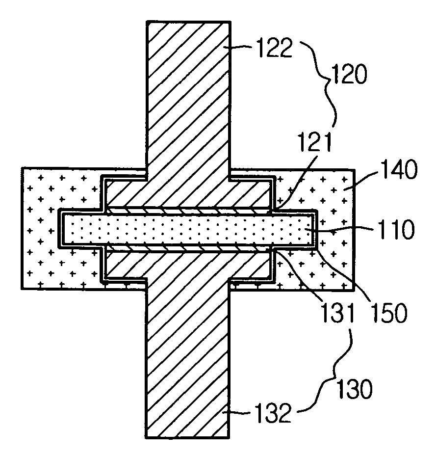
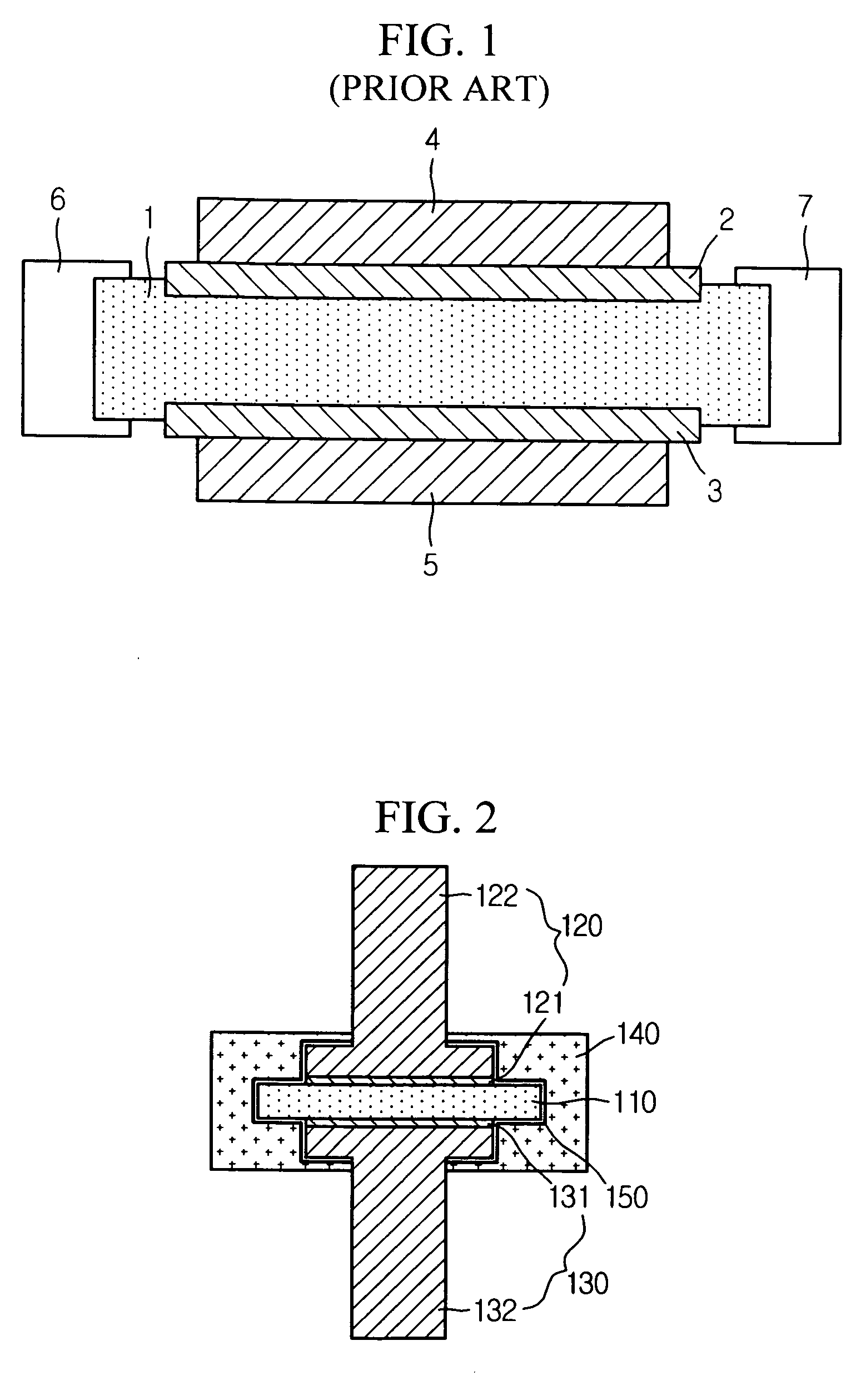
[0038]FIG. 2 is a sectional view showing a PTC (Positive Temperature Coefficient) current limiting device according to the present invention.

[0039] Referring to FIG. 2, the PTC current limiting device of this embodiment includes a PTC element 110, a pair of electrode units 120, 130 arranged so that the PTC element 110 is interposed between them, and a molding part 140 prepared around the PTC element 110 and the electrode units 120, 130.

[0040] The PTC element 110 is used for restraining overcurrent in a power system by abruptly increasing an electric resistance at a specific temperature value as a temperature of surroundings rises.

[0041] The PTC element 110 may have different properties according to a current to be limited, but in this embodiment the PTC element 110 preferably has a specific resistance of 100 Ωm or below at 25° C., and the specific resistance at a switching temperature that Joule heat is generated due to the supply of current preferably becomes at least 105 times a...

second embodiment

[0062]FIG. 6 shows a PTC current limiting device according to the present invention. In FIG. 6, the same reference numeral as in the former drawings designates the same component having the same function, and not described in detail.

[0063] Referring to FIG. 6, the PTC current limiting device of this embodiment further includes a pressing means for pressing the electrode units 120, 130 toward the PTC element 110. The pressing means includes a housing 610, and elastic members 620, 630.

[0064] The housing 610 receives the molding part 140, and in this way receives the entire PTC element 110, the entire contact electrodes 121, 131, and a part of the current leads 122, 132. A part of the current leads 122, 132 is extended outward through the housing 610 and connected to a power system.

[0065] The elastic members 620, 630 are supported against an inner surface of the housing 610, and they are configured to surround outer circumferences of the current leads 122, 132 and press the molding p...

third embodiment

[0076]FIG. 8 shows a PTC current limiting device according to the present invention. In FIG. 8, the same reference numeral as in the former drawings designates the same component having the same function, and not described in detail.

[0077] Referring to FIG. 8, the PTC current limiting device of this embodiment has a molding part with a structure different from the PTC current limiting device of the first embodiment. That is to say, the molding part of this embodiment includes a first insulator 180 made of floating insulating material, and a second insulator 190 prepared to surround the first insulator 180.

[0078] The first insulator 180 may be configured to surround the entire PTC element 110, the entire contact electrodes 121, 131, and a part or all of the current leads 122, 132. Thus, the first insulator 180 may give a more effective function of preventing arc generation or flashover.

[0079] The first insulator 180 is configured to directly surround the PTC element 110 so that arc...


PUM


Abstract

Disclosed is a PTC (Positive Temperature Coefficient) current limiting device for limiting a current by use of PTC characteristics, which includes a PTC element having the PTC characteristics; a pair of electrode units arranged on both sides to face each other with the PTC element being interposed therebetween; and a molding part prepared around the PTC element and the electrode units to surround at least an interface region between the PTC element and the electrode units, the molding part being made of elastic insulating material. The molding part is made of an elastic insulating material or any insulating materials selected from vacuum, gas and oil. Thus, this device may effectively restrain an arc generated while limiting overcurrent or short circuit current, and also prevent flashover between electrodes.

Description

BACKGROUND OF THE INVENTION [0001] 1. Field of the Invention [0002] The present invention relates to a PTC (Positive Temperature Coefficient) current limiting device, and more particularly a PTC current limiting device capable of preventing arc generated between a PTC element and a contact electrode or flashover between contact electrodes. [0003] 2. Description of the Related Art [0004] Generally, a circuit breaker is widely used for preventing a short circuit of a high or low voltage system. A frequency of electricity currently used is 60 Hz, and its one phase may be changed into 16.7 ms. If such one phase is defined as one cycle, a conventional circuit breaker takes a long time, namely at least several cycles for circuit breaking, and does not have a current limiting function against an estimated fault current value, so a ripple effect for the fault is lasting relatively longer. In addition, in case of failing to break a short circuit current, serious effects are given to surround...

Claims


Application Information

Patent Timeline
IPC IPC(8): H01C7/13
CPCH01C1/06H01C1/1406H01C7/027
Inventor KANG, JONG-SUNGKIM, JU-DAMLEE, BANG-WOOKLEE, YOUNG-JUNCHOE, WON-JOONHAN, JUN-KOO
Owner LS IND SYETEMS CO LTD
Why Eureka
Try Eureka