
Methods and apparatus for electro-optical hybrid telemetry

a hybrid telemetry and electrooptical technology, applied in the field of electrooptical hybrid telemetry, can solve the problems of limited use of fiber optics for two-way communication between surface systems and downhole tools, laser diodes and light emitting diodes degrade rapidly or not operate properly at high temperatures, etc., to facilitate single-fiber input/output and facilitate single-fiber input and output.

Inactive Publication Date: 2006-07-13
SCHLUMBERGER TECH CORP
View PDF13 Cites 46 Cited by
  • Summary
  • Abstract
  • Description
  • Claims
  • Application Information

AI Technical Summary

Benefits of technology

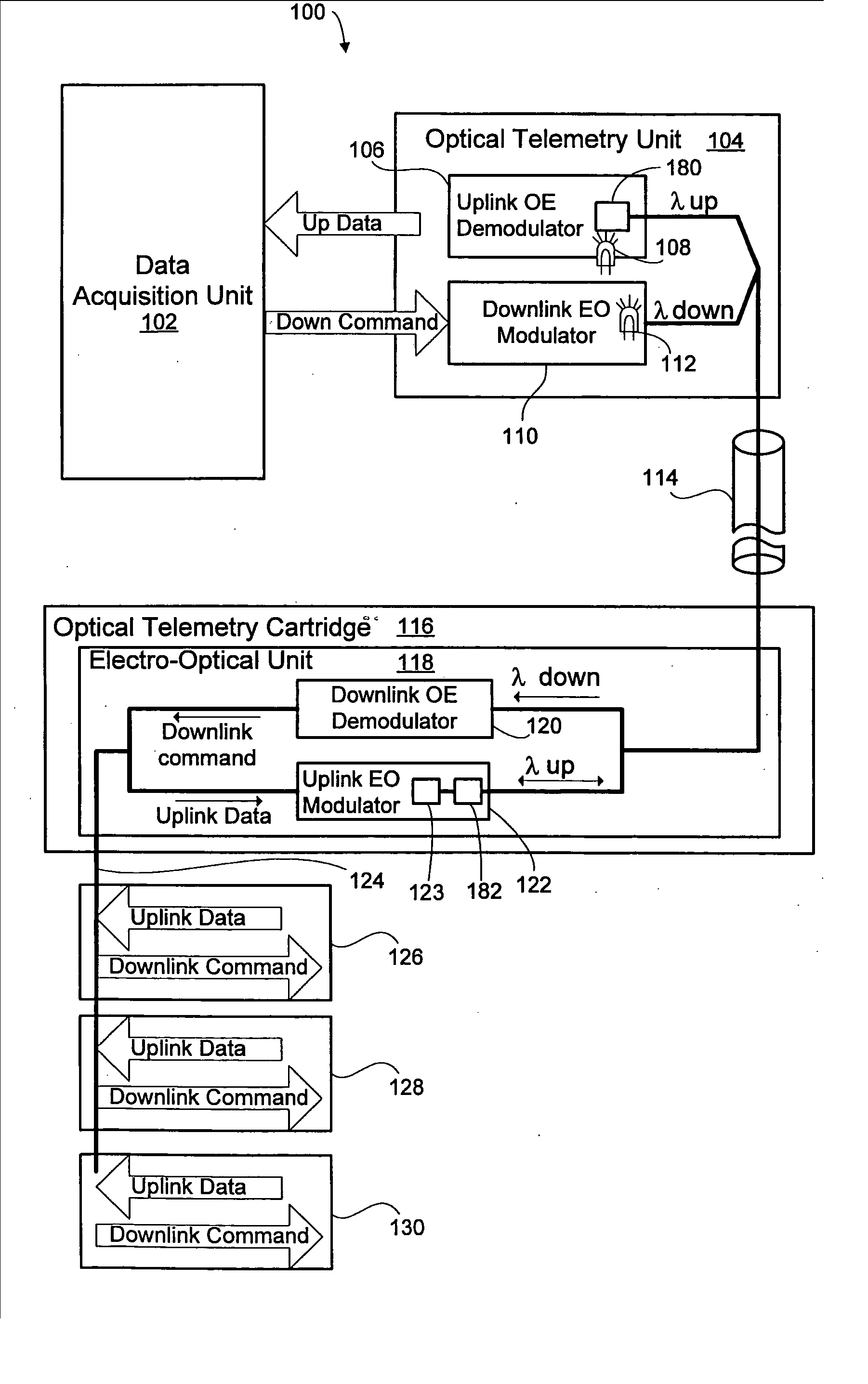
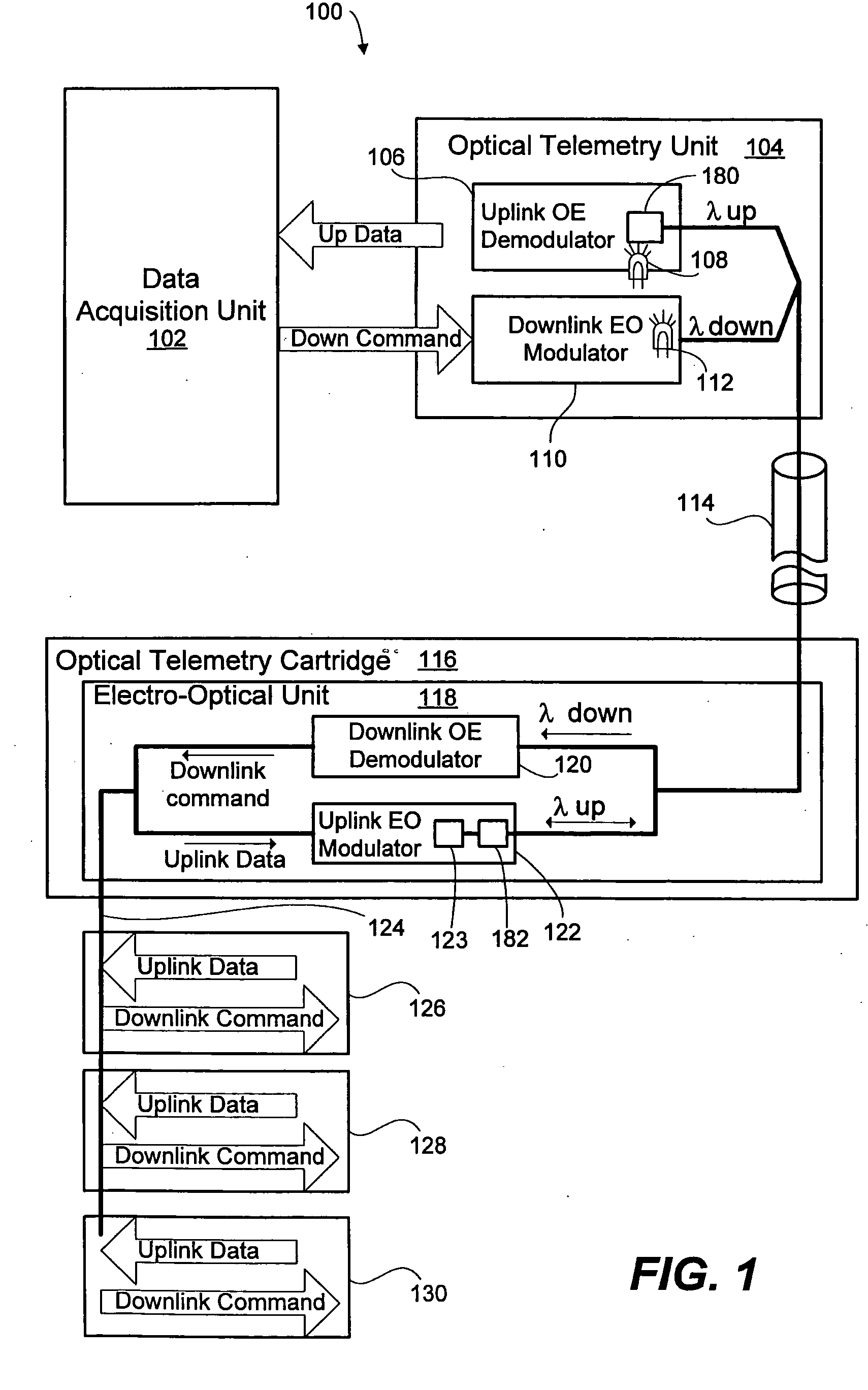
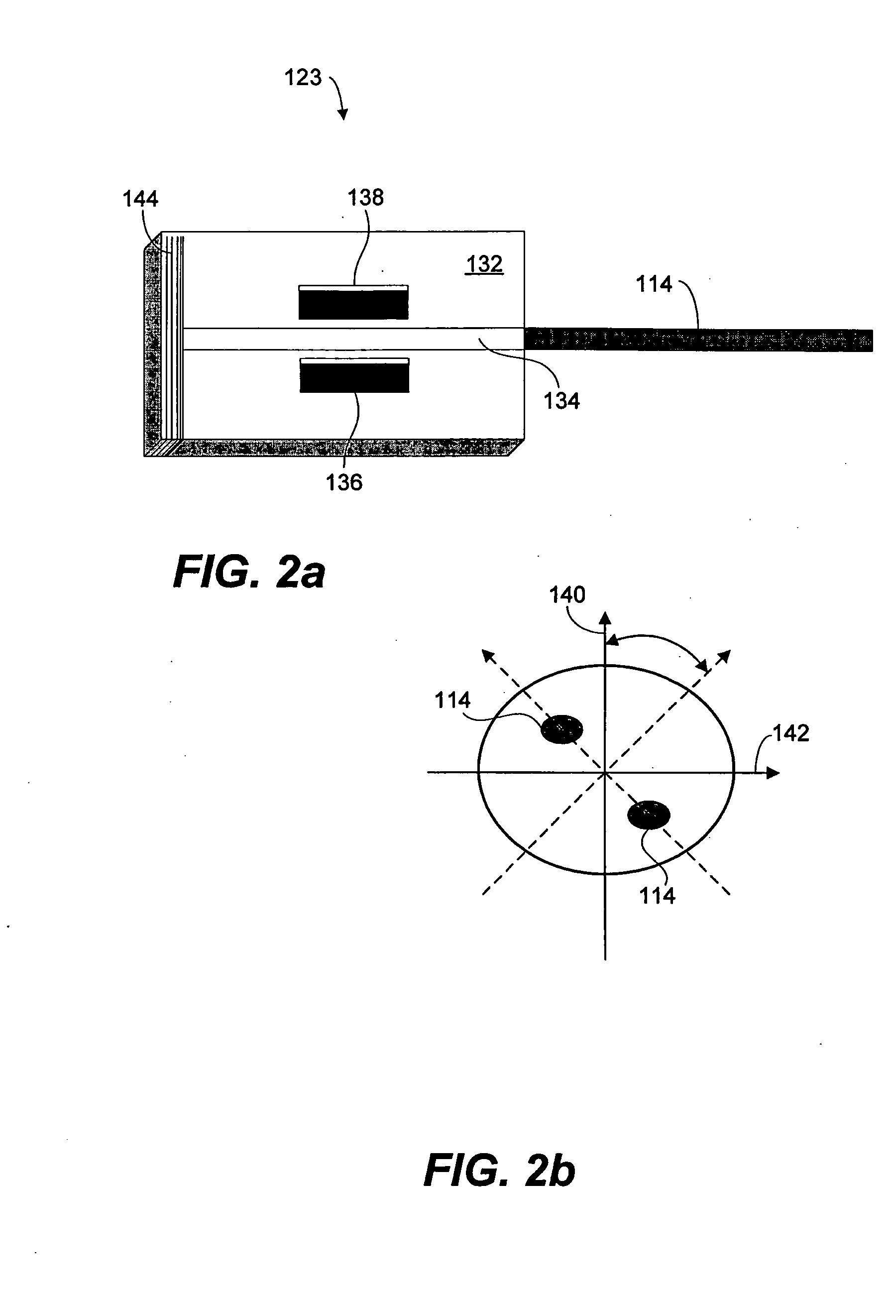
[0007] According to some aspects, the plurality of downhole tools communicate with the surface acquisition data unit exclusively via the fiber optic interface. Moreover, the fiber optic interface may comprise a single fiber, bi-directional system. The surface optical telemetry unit may include an optical source and the downhole optical telemetry cartridge comprises a lithium niobate modulator. The optical source may be located exclusively at the surface. According to some embodiments, the lithium niobate modulator comprises a lithium niobate substrate, a waveguide, and an optical circulator. The optical circulator facilitates a single-fiber input / output. The lithium niobate modulator may also comprises a lithium niobate substrate, a waveguide, and a reflector to facilitate single-fiber input and output. The lithium niobate modulator may further comprise a polarization maintaining fiber rotated an odd multiple of approximately 45 degrees from a waveguide axis. The downhole optical telemetry cartridge may comprise a downhole optical source.

Problems solved by technology

However, many downhole applications require high temperature operations, and optical devices such as laser diodes and light emitting diodes (LEDs) degrade rapidly or do not operate properly at high temperatures.
Therefore, use of fiber optics for two-way communication between surface systems and downhole tools has been limited.

Method used


Image

  • Methods and apparatus for electro-optical hybrid telemetry
  • Methods and apparatus for electro-optical hybrid telemetry
  • Methods and apparatus for electro-optical hybrid telemetry

Examples


Embodiment Construction

[0036] Illustrative embodiments and aspects of the invention are described below. It will of course be appreciated that in the development of any such actual embodiment, numerous implementation-specific decisions must be made to achieve the developers' specific goals, such as compliance with system-related and business-related constraints, that will vary from one implementation to another. Moreover, it will be appreciated that such a development effort might be complex and time-consuming, but would nevertheless be a routine undertaking for those of ordinary skill in the art having the benefit of this disclosure.

[0037] The present invention contemplates methods and apparatus facilitating optical communications between downhole tools and sensors, and surface systems. The use of fiber optics between downhole tools and the surface provides higher data transmission rates than previously available. The principles described herein facilitate active and passive fiber optic communications b...


PUM


Abstract

Hybrid electrical-optical telemetry systems and methods are disclosed. The methods and systems facilitate faster data transmission rates between the surface and downhole tools and sensors. The methods and systems may also include a downhole electrical bus for inter-tool and intra-tool communication to facilitate limited changes to existing downhole equipment. Some embodiments of the hybrid electrical-optical telemetry system include a light source at the surface and a downhole modulator. Some embodiments also include redundant, selectable optical systems. The methods and systems may operate via a single optical input / output cable.

Description

FIELD OF THE INVENTION [0001] The present invention relates generally to methods and apparatus for gathering data from sub-surface formations. More particularly, the present invention relates to methods and apparatus for communicating between various downhole tools traversing a sub-surface formation and a surface data acquisition unit. BACKGROUND OF THE INVENTION [0002] Logging boreholes has been done for many years to enhance recovery of oil and gas deposits. In the logging of boreholes, one method of making measurements underground includes attaching one or more tools to a wireline connected to a surface system. The tools are then lowered into a borehole by the wireline and drawn back to the surface (“logged”) through the borehole while taking measurements. The wireline is usually an electrical conducting cable with limited data transmission capability. [0003] Demands for higher data transmission rates for wireline logging tools is growing rapidly because of the higher resolution,...

Claims


Application Information

Patent Timeline
IPC IPC(8): G01V3/00E21B47/12
CPCE21B47/123H04B10/2587E21B47/135H04J14/02H04B10/25
Inventor YAMATE, TSUTOMUVANNUFFELEN, STEPHANEGAYRAL, BRUNOCHEE, SOON SEONGWILSON, COLIN
Owner SCHLUMBERGER TECH CORP
Learn More