Reaction chamber

Inactive Publication Date: 2006-07-13
GE HEALTHCARE BIO SCI CORP
View PDF5 Cites 9 Cited by
  • Summary
  • Abstract
  • Description
  • Claims
  • Application Information

AI Technical Summary

Benefits of technology

[0028]FIG. 2 depicts another embodiment of a two assay reaction system 200 having two assay chambers defined by a semi-rigid, thin-walled case 210, perimeter adhesive layer 230, and substrate 250 having arrays 261 and 262. The thin-walled case has two thin-walled 212 openings, a flat, thin bottom flan

Problems solved by technology

This chamber suffers from being a rigid plastic chamber.
The slide itself has a special coating to provide adequate adhesion, which would be difficult to implement for bioassay slides.
For scanning with the chamber in place, non-flatness of the chamber would warp the glass, which could adversely affect scanning.
Simply adding the reaction components separately to a

Method used


Image

  • Reaction chamber
  • Reaction chamber
  • Reaction chamber

Examples


example 1

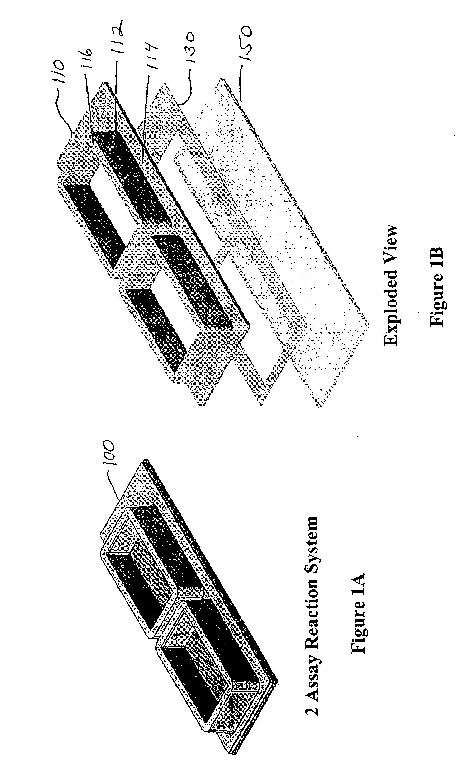
[0074] One example is illustrated in FIG. 1A, with an exploded view in FIG. 1B. The two assay reaction chamber system 100 has two assay chambers defined by a semi-rigid, thin-walled case 110, perimeter adhesive layer 130, and substrate 150. The thin-walled case has two thin-walled 112 openings, a flat, thin bottom flange 114, and rims 116 at the upper end of the thin-walled openings.

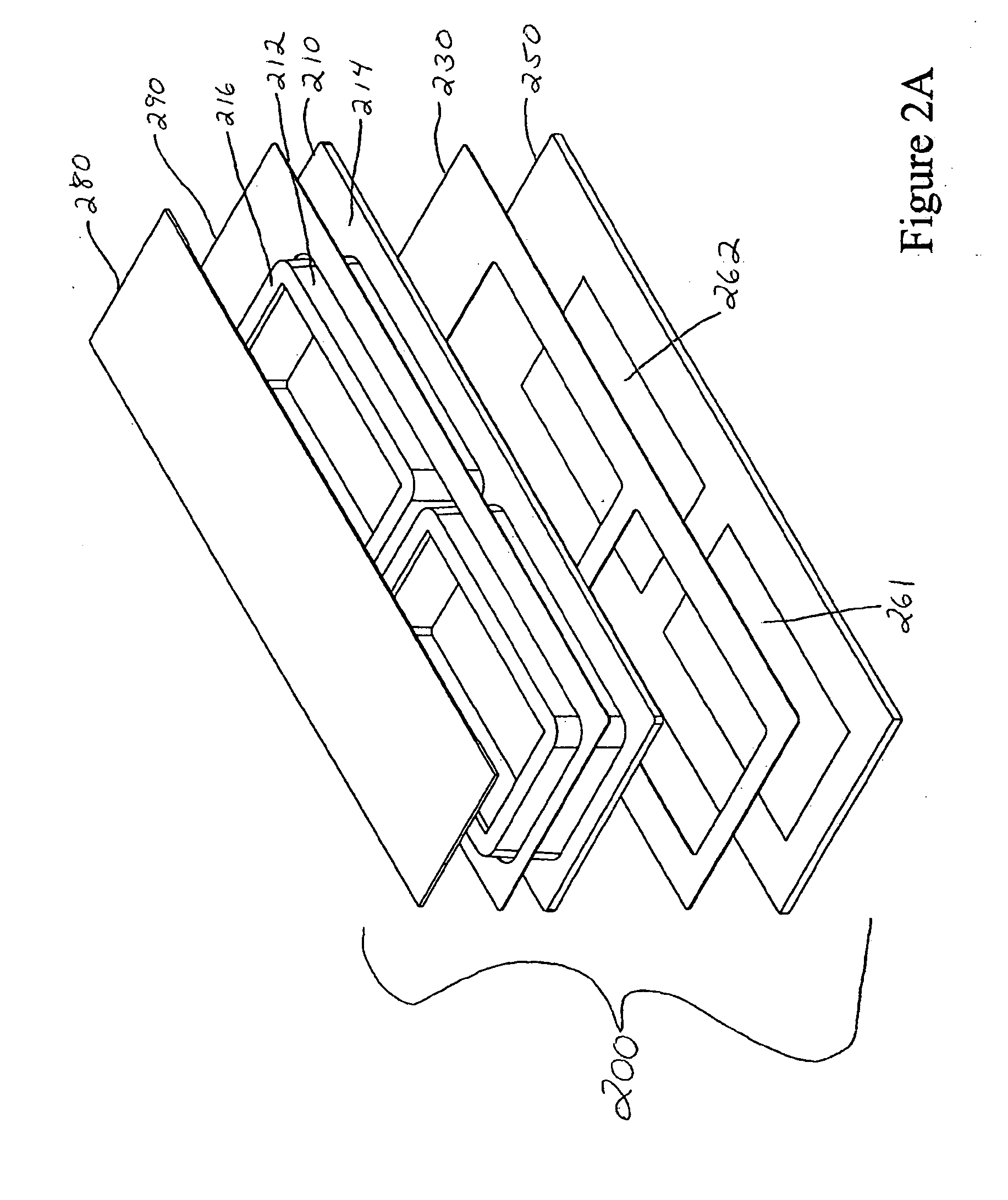
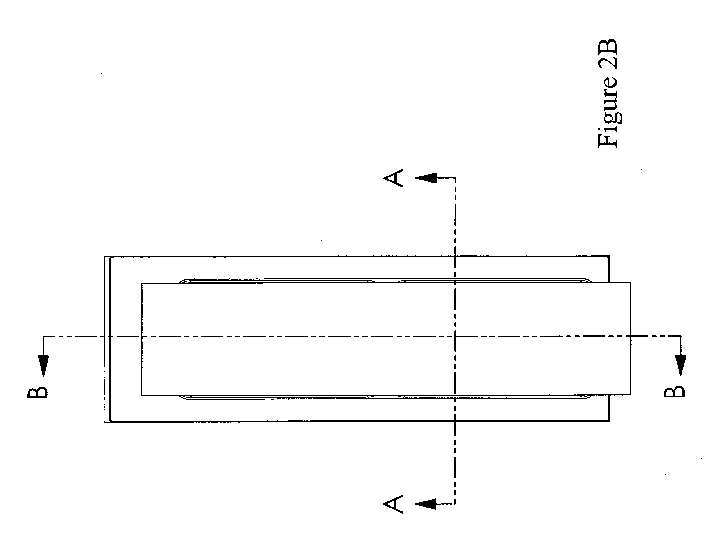
[0075] Another example is illustrated in FIG. 2, with several views displayed in FIGS. 2A through 2D. The two assay reaction system 200 has two assay chambers defined by a semi-rigid, thin-walled case 210, perimeter adhesive layer 230, and substrate 250 having arrays 261 and 262. The thin-walled case has two thin-walled 212 openings, a flat, thin bottom flange 214, and rims 216 at the upper end of the thin-walled openings. A top sealing strip 280 covers the opening of the thin-walled case to prevent evaporation of reaction contents. Also shown is a sheet 290 on top of the bottom flange of the case which...


PUM

PropertyMeasurementUnit
Thicknessaaaaaaaaaa
Sizeaaaaaaaaaa
Flexibilityaaaaaaaaaa

Abstract

The invention describes novel reaction chambers that include a case with at least one opening and a flat bottom flange attached to the first side of a substrate with at least one microarray of materials attached thereto. The case and the substrate are attached through an adhesive layer with at least one perforations such that the at least one microarrays, the at least one perforations and the at least one openings are aligned and forms at least one individual reaction chambers. Methods of using such chambers are disclosed. Also provided are kits including the novel chambers.

Description

CROSS-REFERENCE TO RELATED APPLICATIONS [0001] This application claims priority to U.S. provisional patent application No. 60 / 638,333 filed Dec. 22, 2004 and 60 / 734,951 filed Nov. 9, 2005; the disclosures of which are incorporated herein by reference in their entireties.FIELD OF THE INVENTION [0002] The present invention is directed toward novel reaction chambers, systems and methods of use. More specifically, the invention is directed to novel chambers for use with microarray systems. Methods of using such chambers are also disclosed. BACKGROUND OF THE INVENTION [0003] Microarrays have revolutionized biological research over the past decade. As a result, instrumentation for manufacturing and reading spotted microarrays has been widely commercialized. The initial technology for spotting cDNA has now been extended to include spotting other materials, including small molecules, oligonucleotides, proteins (e.g., enzymes, antibodies, etc.), whole cells, and tissue specimens. To a large ...

Claims


Application Information

Patent Timeline
IPC IPC(8): C12Q1/68G01N33/53C12M1/34
CPCB01J2219/00286B01J2219/00527B01J2219/00585B01J2219/00596B01J2219/00605B01J2219/0061B01J2219/00612B01J2219/00659B01J2219/00662B01J2219/00707B01J2219/00722B01J2219/00725B01J2219/00731B01L3/5085B01L3/50853B01L2200/0689B01L2200/12B01L2300/044B01L2300/0636B01L2300/0822B01L2300/0829B01L2300/0851G01N2035/00158
Inventor KAHN, PETER A.ANDERSON, CLIFFORD L.
Owner GE HEALTHCARE BIO SCI CORP
Why Eureka
Try Eureka