Liquid treating apparatus

a technology of liquid treatment apparatus and etching reaction, which is applied in the direction of moving filter element filter, separation process, filtering, etc., can solve the problems of defective product manufacturing, etching reaction progressing to generate stains, and inaccurate wiring pitch cannot be obtained in case, so as to prevent defective products from being manufactured, prevent defective products, and ensure the effect of treatmen

Inactive Publication Date: 2006-07-13
MITSUI MINING & SMELTING CO LTD +1
View PDF2 Cites 7 Cited by
  • Summary
  • Abstract
  • Description
  • Claims
  • Application Information

AI Technical Summary

Benefits of technology

[0041] Accordingly, the solution, which is discharged by means of the treating solution discharging device and floating like a mist, can be prevented from coming in contact with the surface treated substance before the liquid treating start position A, in a state in which the discharged solution is almost isolated through the treating solution contact prevention chamber. Consequently, it is possible to reliably carry out a treatment with the treating solution. Thus, it is possible to prevent a defective product from being generated.
[0043] Consequently, it is possible to prevent the etchant floating like the mist from excessively treating the surface of the surface treated substance in contact therewith. Thus, it is possible to prevent a defective product from being generated.
[0093] The surface treated substance passes through the inside of the treating solution contact prevention chamber, which is disposed in the outer position in the direction of the delivery of the surface treated substance from the liquid treating terminal position, for example, the inside of the treating solution contact prevention chamber, which is disposed on the upstream side of the liquid treating start position A to be the liquid treating terminal position. Therefore, it is possible to prevent the discharged solution from coming in contact with the surface treated substance before the liquid tre

Problems solved by technology

For this reason, particularly, an accurate wiring pitch cannot be obtained in case of a small pitch.
In these cases, there is a possibility that a

Method used


Image

  • Liquid treating apparatus
  • Liquid treating apparatus
  • Liquid treating apparatus

Examples


Embodiment Construction

[0110] An embodiment (example) of the present invention will be described below in more detail with reference to the drawings.

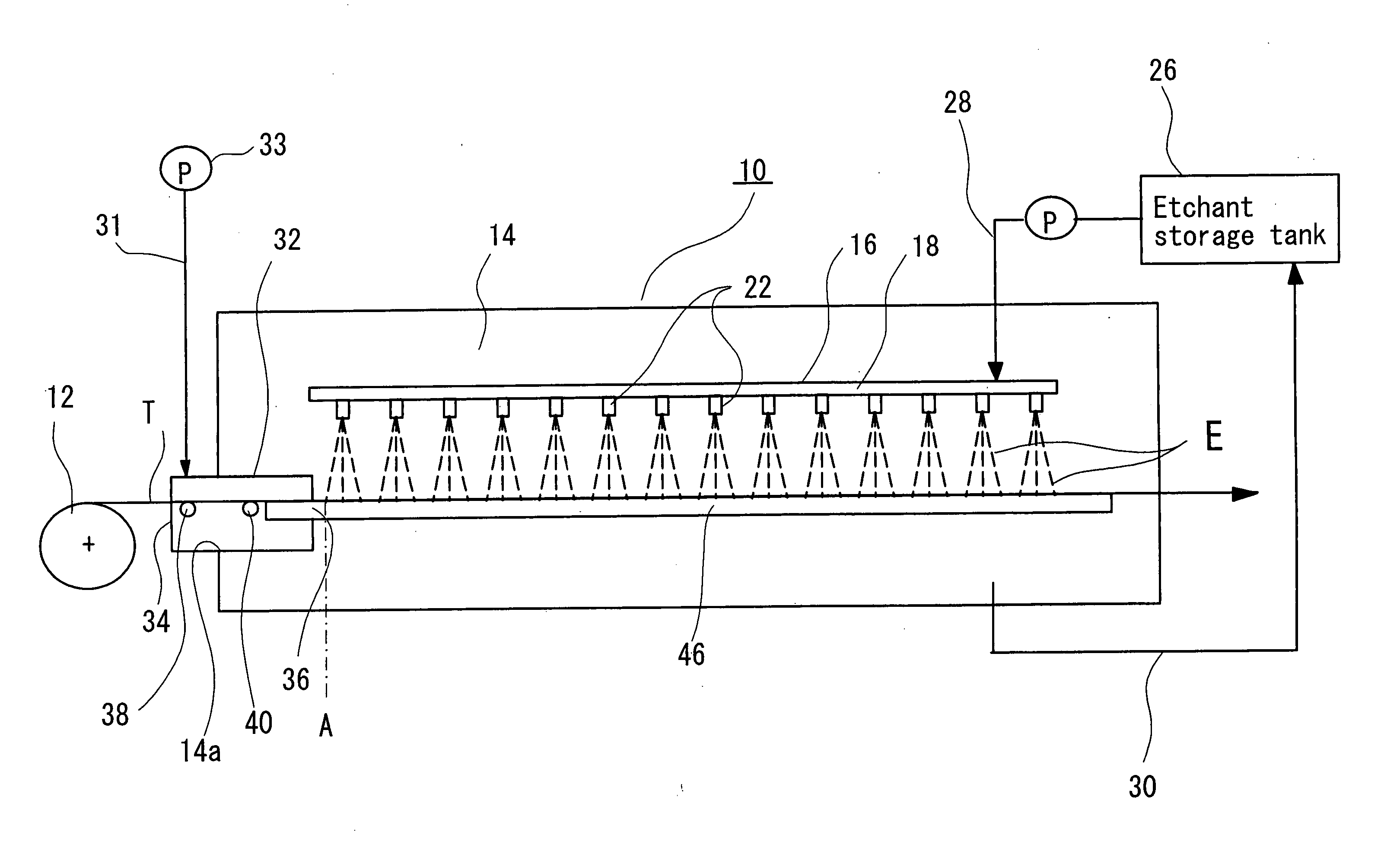
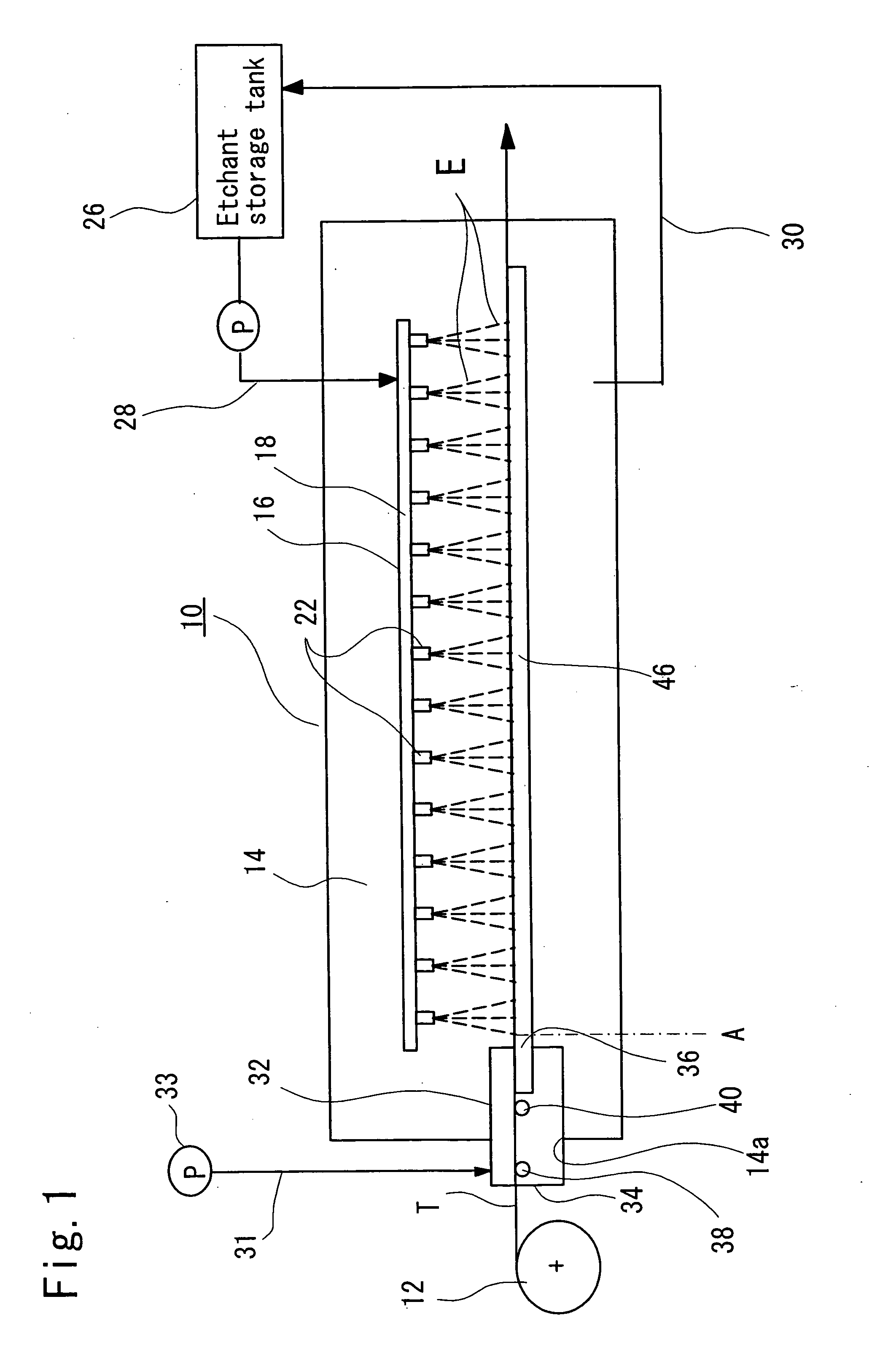
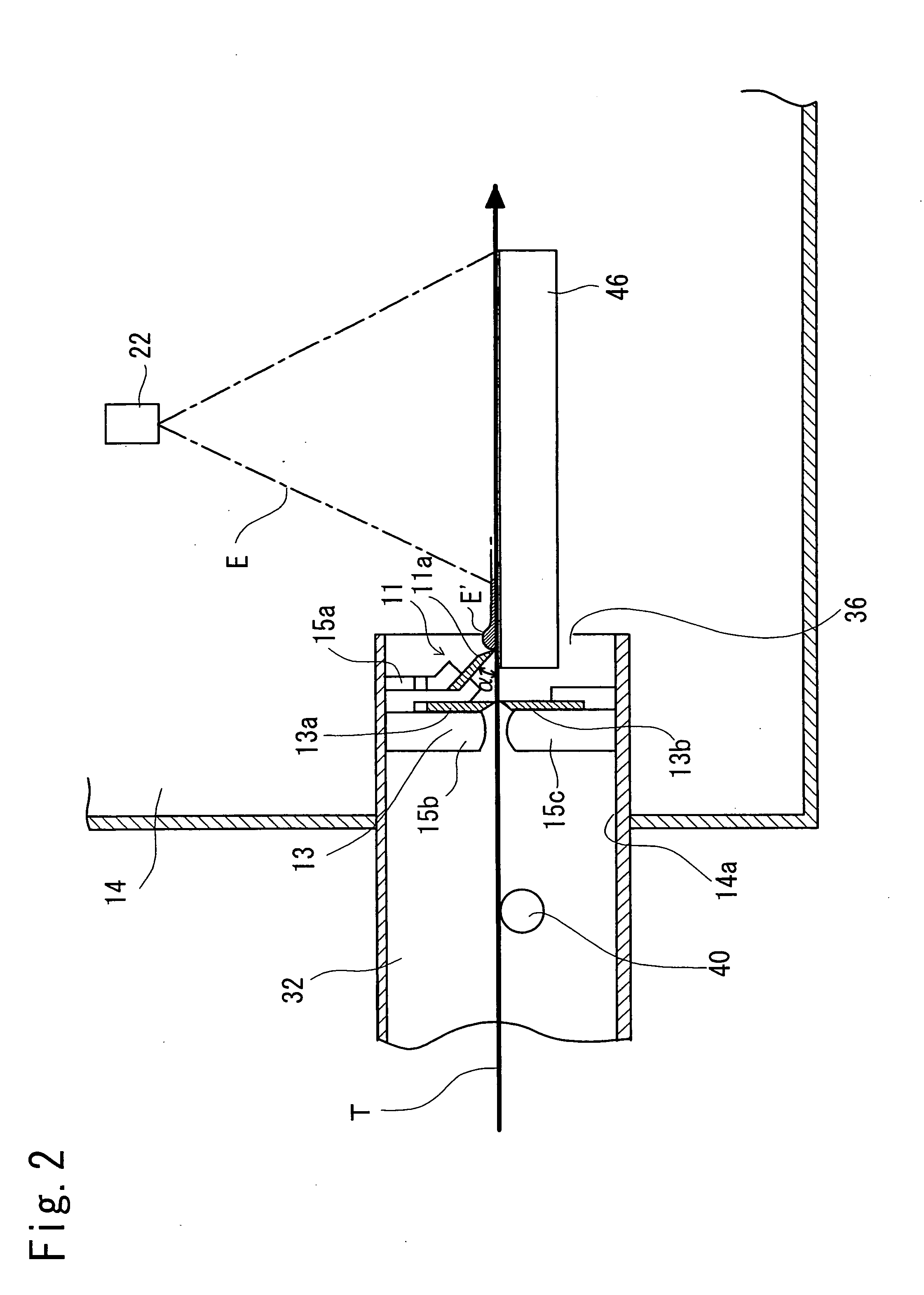
[0111]FIG. 1 is a schematic view showing an example in which a liquid treating apparatus according to the present invention is applied to a device for etching a film carrier tape for mounting electronic component to be a sheet-like substance to be surface treated, and FIG. 2 is a schematically partial enlarged view.

[0112] In FIGS. 1 and 2, 10 denotes a device for etching a film carrier tape according to the present invention (which will be hereinafter referred to as an “etching device”) as a whole.

[0113] The etching device 10 is used as a substance to be surface treated, that is, a film carrier tape T formed by exposing a desirable pattern shape through the irradiation of an ultraviolet ray onto a photoresist by means of a photomask and dissolving and removing the exposed photoresist portion with a developer, thereby exposing a copper layer portion which i...


PUM

PropertyMeasurementUnit
Angleaaaaaaaaaa

Abstract

A liquid treating apparatus includes an etchant discharging nozzle for discharging a treating solution (E) onto an upper surface of a film carrier tape for mounting an electronic component (T) from above and a treating solution contact prevention chamber disposed on an upstream side of a liquid treating start position (A) in which an etchant (E) discharged onto an upper surface of the film carrier tape (T) through an etchant discharging nozzle starts etching and serving to prevent the discharged solution from coming in contact with the film carrier tape (T) before the liquid treating start position (A). The apparatus also includes a liquid sealing lip member of a first infiltration preventing member and an upper lip component and a lower lip component of a second infiltration preventing member disposed in the treating solution contact prevention chamber.

Description

FIELD OF THE INVENTION [0001] The present invention relates to a liquid treating apparatus to be used in a liquid treating process for discharging a treating solution to a space under pressure in the manufacture of a film carrier tape for mounting electronic component (a TAB (Tape Automated Bonding) tape, a COF (Chip on Film) tape, a T-BGA (Tape Ball Grid Array) tape, a CSP (Chip Size Package) tape, an ASIC (Application Specific Integrated Circuit) tape, a 2-metal (double-sided wiring) tape, a multilayer wiring tape or the like (which will be hereinafter referred to as a “film carrier tape”). DESCRIPTION OF THE RELATED ART [0002] With the development of electronics industry, there has been rapidly increased a demand for a printed wiring board for mounting an electronic component such as an IC (integrated circuit) chip or an LSI (large scale integrated circuit). However, there have been required a reduction in a size and weight and an enhancement in a function in electronic equipment...

Claims


Application Information

Patent Timeline
IPC IPC(8): H01L21/302
CPCH01L21/6708H05K1/0393H05K3/0085H05K3/068H05K2203/075H05K2203/1147H05K2203/1545B01D33/80B01D33/44
Inventor NARABAYASHI, TETSUYUKIKUNIMOTO, SHINJIKASAI, MAKOTOTODA, KENJI
Owner MITSUI MINING & SMELTING CO LTD
Why Eureka
Try Eureka