Mechanical serpentine device

a serpentine device and mechanical technology, applied in the direction of mechanical control devices, process and machine control, instruments, etc., can solve the problems of difficult intraluminal catheter deployment, large distance between the catheter entrance point and the target site, and large volume of the serpentine robot, etc., to achieve the effect of improving the operating characteristics

Inactive Publication Date: 2006-07-20
RAYTHEON SARCOS LLC
View PDF76 Cites 73 Cited by
  • Summary
  • Abstract
  • Description
  • Claims
  • Application Information

AI Technical Summary

Benefits of technology

[0013] In light of the problems and deficiencies inherent in the prior art, the present invention seeks to overcome these by providing a serpentine device, wherein in one exemplary embodiment the serpentine device comprises a mechanical serpentine robot and / or, in another exemplary embodiment, the serpentine device comprises a segmented guidewire, each having improved operating characteristics.

Problems solved by technology

Prior art serpentine robots are bulky, heavy, and consist of many components that require complex algorithms to control.
However, intraluminal deployment of a catheter can often be difficult.
The distance between the catheter entrance point and the target site is often considerable.
Moreover, the size of the lumen of the vessels leading to the target site are typically quite small.
Therefore, the path which the catheter must follow are often narrow and tortuous.
As the guidewire is advanced into the anatomy, internal frictional resistance resulting from the typically numerous turns and attendant surface contacts, decreases the ability to turn the guidewire and to advance the guidewire further within the luminal space.
This, in turn, may lead to a more difficult and prolonged procedure, or, more seriously, failure to access the desired anatomy at the target location and thus a failed procedure.
However, if the guidewire does not also have good torque characteristics (torsional stiffness), the user will not be able to twist the proximal end in order to rotate the distal tip of the guidewire to guide its advance as required.

Method used


Image

  • Mechanical serpentine device
  • Mechanical serpentine device
  • Mechanical serpentine device

Examples


Embodiment Construction

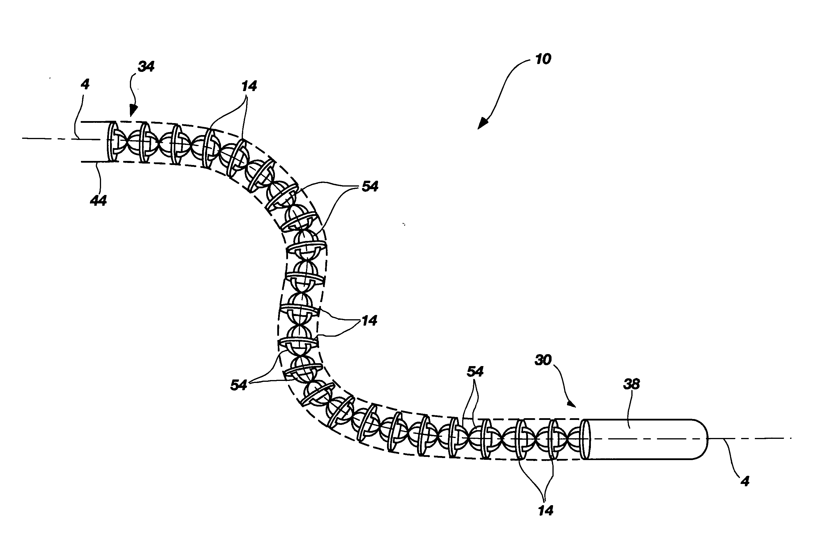
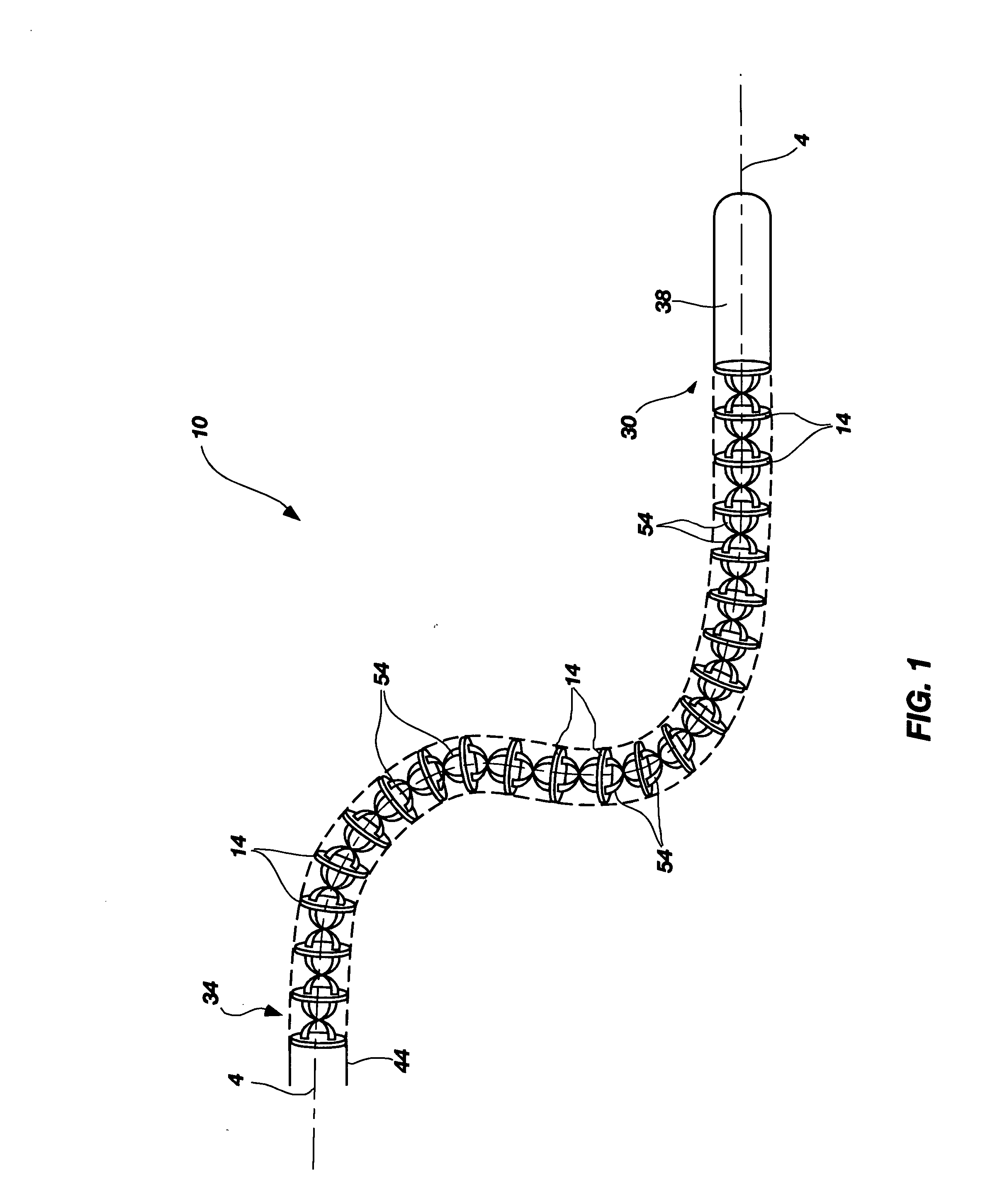
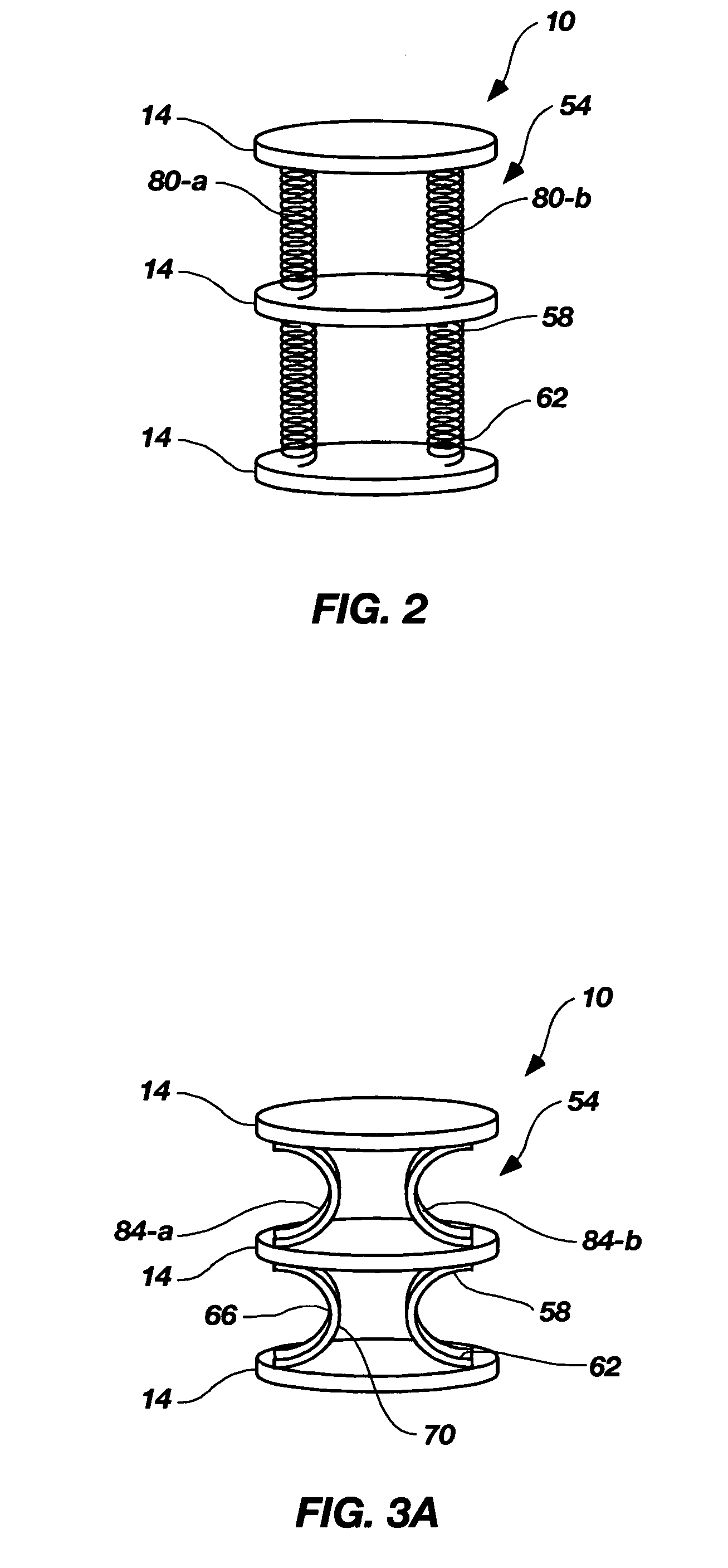
[0037] The following detailed description of exemplary embodiments of the invention makes reference to the accompanying drawings, which form a part hereof and in which are shown, by way of illustration, exemplary embodiments in which the invention may be practiced. While these exemplary embodiments are described in sufficient detail to enable those skilled in the art practice the invention, it should be understood that other embodiments may be realized and that various changes to the invention may be made without departing from the spirit and scope of the present invention. Thus, the following more detailed description of the embodiments of the present invention, as represented in FIGS. 1 through 10-C, is not intended to limit the scope of the invention, as claimed, but is presented for purposes of illustration only and not limitation to describe the features and characteristics of the present invention, to set forth the best mode of operation of the invention, and to sufficiently e...


PUM


Abstract

A serpentine device having a proximal end and a distal end comprising a series of discs arrayed in succession and on center along a common, neutral axis, wherein the discs comprise a first and second surface; and at least one flexible interconnect extending between and connecting each disc to any succeeding disc according to a pre-determined connection configuration, wherein the interconnects are indirectly connected to one another through the discs and configured to provide torsional and bending support to each of the discs connected thereto under an applied load, thus achieving a continuum of flexibility along an entire length of the serpentine device, as well as to facilitate the torquability of the serpentine device. The serpentine device may further comprise a bendable member and at least one transfer element configured to perform one or more transfer functions, namely the transfer of energy, work, fluid, electricity, light energy, sound energy, matter, etc. from one location to another location, and particularly from a source to one or more of the discs of the serpentine device. An actuation system is also featured, which is configured to selectively actuate the discs in a pre-determined direction in three-dimensional space.

Description

[0001] This application claims priority to U.S. Provisional Patent Application No. 60 / 633,035, filed Dec. 2, 2005 in the U.S. Patent and Trademark Office, entitled, “Segmented Guidewire,” which application is incorporated by reference in its entirety herein.FIELD OF THE INVENTION [0002] The present invention relates generally to serpentine devices employed for various purposes in various applications or industries, and more particularly to a mechanical serpentine device configured for improved efficiency, dynamic control and performance along its length. The present invention also relates generally to serpentine robots and guidewires, as variations of serpentine devices, wherein at least some of the concepts employed in constructing and operating a serpentine robot may apply to the same for guidewires. BACKGROUND OF THE INVENTION AND RELATED ART [0003] Serpentine devices, such as serpentine robots or guidewires, are designed to exhibit snake-like movements with multiple degrees of f...

Claims


Application Information

Patent Timeline
Patent Type & Authority Applications(United States)
IPC IPC(8): B25J18/00
CPCY10T74/20305B25J18/06
Inventor JACOBSEN, STEPHEN C.MARKUS, DAVID T.MARCEAU, DAVIDZURN, SHAYNE
Owner RAYTHEON SARCOS LLC
Why Eureka
Try Eureka