
Quantum dot phosphor for light emitting diode and method of preparing the same

a light-emitting diode and quantum dot technology, applied in the field of quantum dot phosphor for light-emitting diodes and a method of preparing the same, can solve the problems of reducing the light-emitting efficiency of quantum dots, unconfirmed properties of polymers for use in diodes, etc., and achieve excellent light-emitting efficiency

Inactive Publication Date: 2006-07-20
SAMSUNG ELECTRONICS CO LTD
View PDF11 Cites 154 Cited by
  • Summary
  • Abstract
  • Description
  • Claims
  • Application Information

AI Technical Summary

Benefits of technology

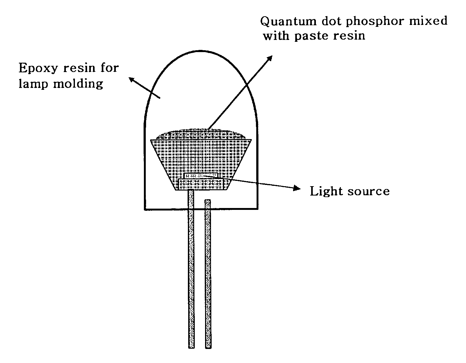
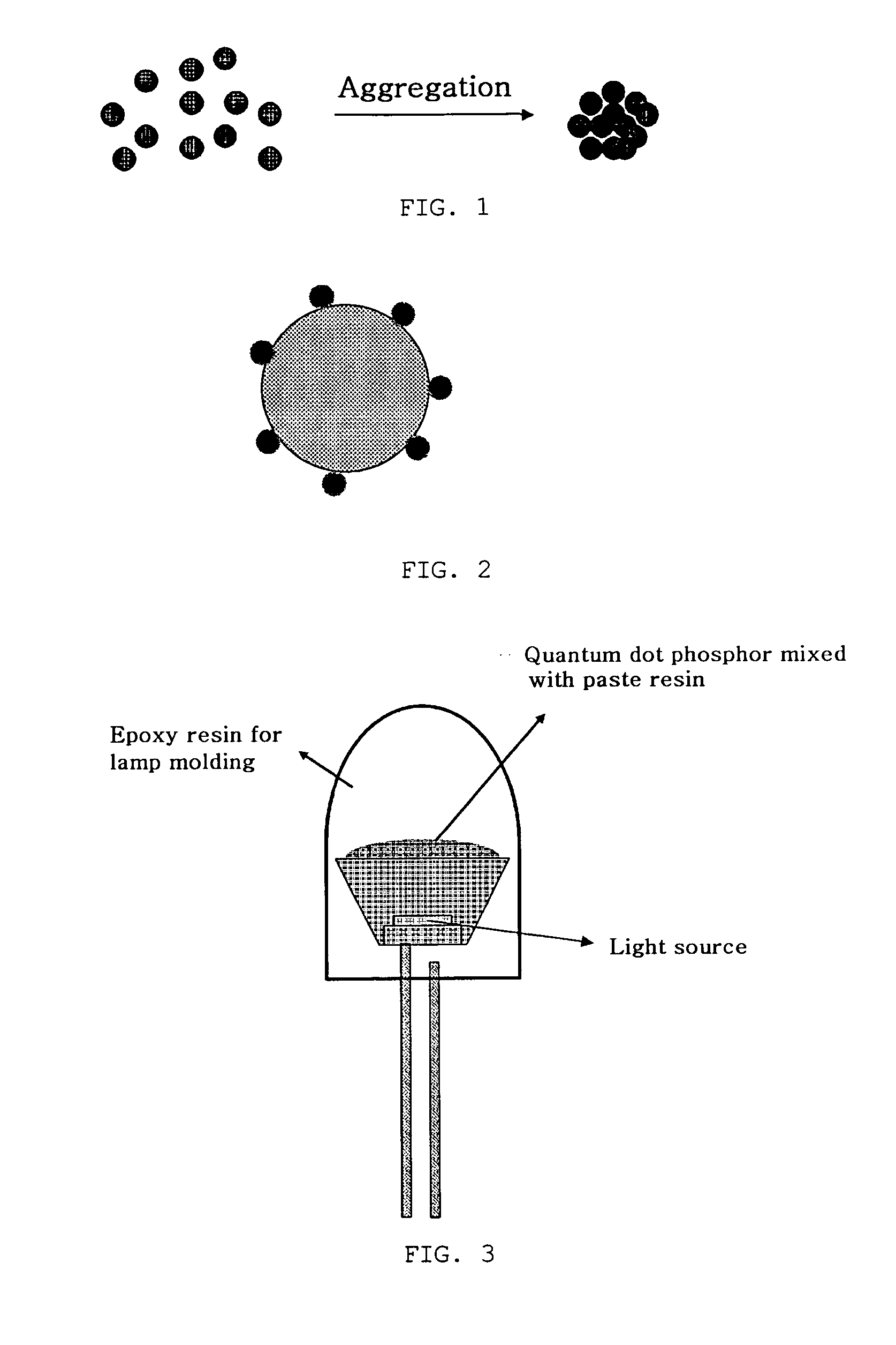
The present invention provides a light emitting diode with quantum dots that are well dispersed and not aggregated upon dispensing a phosphor paste. This results in improved light emitting efficiency. The invention also provides a method for preparing the quantum dot phosphor by dispersing quantum dots in a dispersion solvent and mixing them with a solid substrate, followed by drying to remove the solvent. The light emitting diode includes the quantum dot phosphor mixed with a paste resin, an epoxy resin for lamp molding, and a light source. The method of manufacturing the light emitting diode involves dispensing the quantum dot phosphor mixed with the paste resin on the light emitting diode and curing it.

Problems solved by technology

However, in conventional processes of manufacturing a light emitting diode, a monomer having high affinity to the organic ligand of the quantum dots is not used, and also, whether the properties of the polymer are suitable for use in a diode may be unconfirmed.
However, in the case where the quantum dots are mixed with the paste resin, the quantum dots are difficult to disperse well in the resin due to low affinity to the resin, and thus, may aggregate as shown in FIG. 1, resulting in reduced light emitting efficiency of the quantum dots.

Method used


Image

  • Quantum dot phosphor for light emitting diode and method of preparing the same
  • Quantum dot phosphor for light emitting diode and method of preparing the same
  • Quantum dot phosphor for light emitting diode and method of preparing the same

Examples


example 1

[0054] (1) Preparation of Quantum Dot Phosphor Supported On KBr Substrate

[0055] 5 ml of a solution of 1 wt % CdSe / CdS nanocrystals synthesized in Preparative Example 1 dispersed in toluene were added to 1 g of KBr powders. While toluene was gradually evaporated at room temperature, the nanocrystals and the powders were well mixed and kneaded. After the solution was dried, the powders were loaded into an oven at 80° C. for 6 hr, to completely dry toluene, thereby preparing a quantum dot phosphor supported on a KBr substrate. The dried KBr powders represented the color of CdSe / CdS nanocrystals, and the nanocrystals were present in the efficiently dispersed state on the KBr substrate.

[0056] (2) Fabrication of Light Emitting Diode

[0057] The quantum dot phosphor comprising nanocrystals dispersed and supported on KBr powders was mixed with 2 g of a solution of an epoxy resin and a curing agent mixed at a weight ratio of 1:1, to prepare a mixture of powders and an epoxy resin. The mixtu...

example 2

[0058] (1) Preparation of Quantum Dot Phosphor Supported On PS Bead Substrate

[0059] 10 ml of 1 wt % plain(hydrophobic)polystyrene microspheres (PS beads) dispersed in an aqueous solution available from Bangs Laboratory were centrifuged and dried. The dried powders were dispersed again in toluene, added with ethanol, centrifuged, and then re-dried, to prepare PS beads without a surfactant. To the PS beads thus separated, 5 ml of a solution of 1 wt % CdSe / CdS nanocrystals synthesized in Preparative Example 1 dispersed in toluene were added. While toluene was gradually evaporated at room temperature, the nanocrystals and the powders were well mixed and kneaded. After the solution was dried, the powders were loaded into an oven at 80° C. for 6 hr, to completely dry toluene, thereby preparing a quantum dot phosphor supported on a PS bead substrate. The dried PS beads represented the color of CdSe / CdS nanocrystals, and the nanocrystals were present in the efficiently dispersed state on t...

example 3

[0062] (1) Preparation of Quantum Dot Phosphor Supported on Inorganic Phosphor

[0063] 5 ml of a solution of 1 wt % CdSe / CdS nanocrystals synthesized in Preparative Example 1 dispersed in toluene were added to 1 g of LDP-R3 inorganic phosphor((Zn,Cd)S:Ag+In2O3, available from Kasei Optonix). While toluene was gradually evaporated at room temperature, the nanocrystals and the phosphor were well mixed and kneaded. After the solution was dried, the phosphor was loaded into an oven at 80° C. for 6 hr, to completely dry toluene, thereby preparing a sample 1. Separately, another phosphor having nanocrystals dispersed and supported thereon was prepared in the same manner as in the preparation of the sample 1, and then, dispensing and drying of nanocrystals were further performed once, to prepare a sample 2.

[0064] (2) Fabrication of Light Emitting Diode

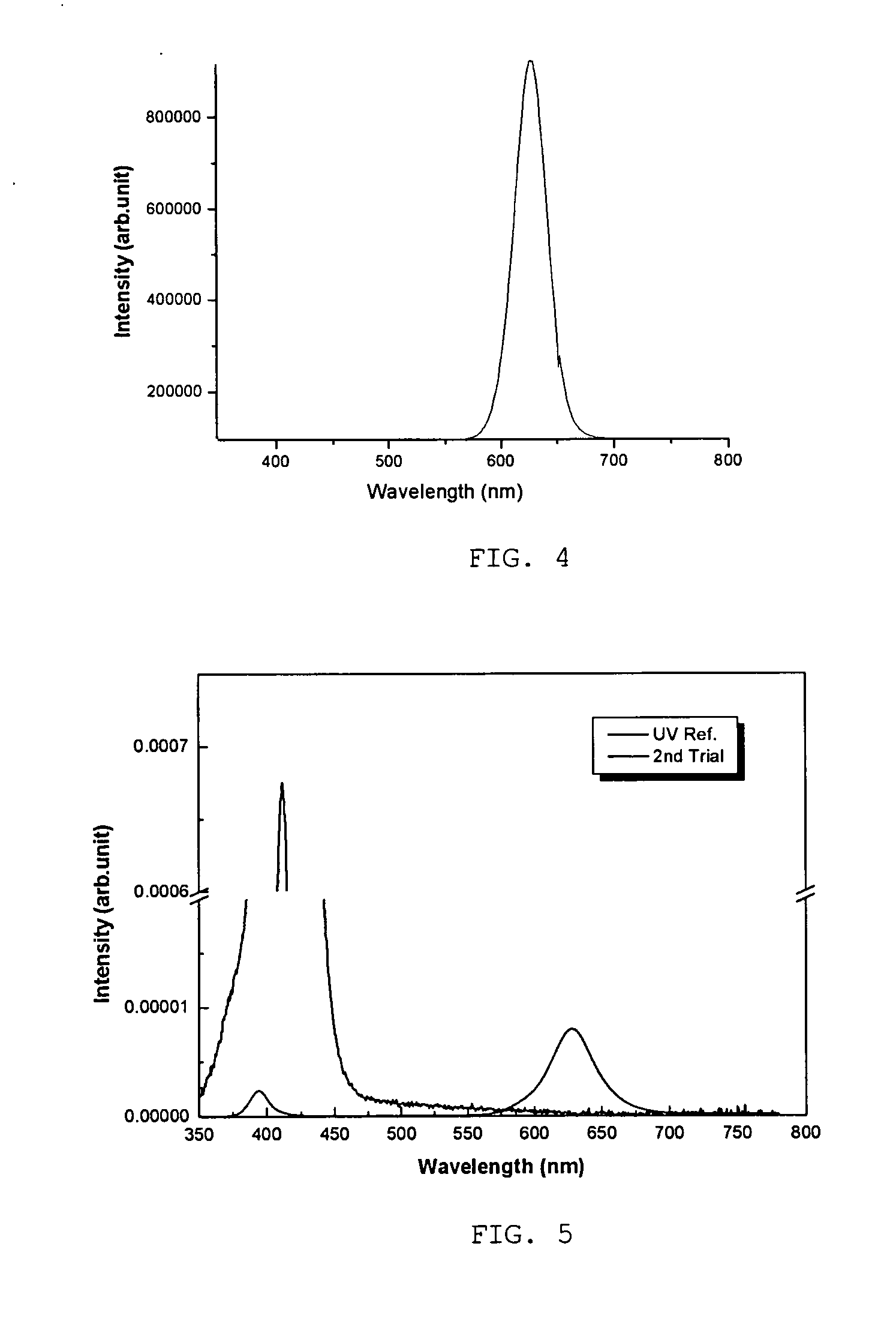
[0065] LDP-R3 inorganic phosphor, and the samples 1 and 2 were each mixed with 2 g of a solution of an epoxy resin and a curing agent mixed...


PUM


Abstract

Disclosed herein is a quantum dot phosphor for light emitting diodes, which includes quantum dots and a solid substrate on which the quantum dots are supported. Also, a method of preparing the quantum dot phosphor is provided. Since the quantum dot phosphor of the current invention is composed of the quantum dots supported on the solid substrate, the quantum dots do not aggregate when dispensing a paste obtained by mixing the quantum dots with a paste resin for use in packaging of a light emitting diode. Thereby, a light emitting diode able to maintain excellent light emitting efficiency can be manufactured.

Description

BACKGROUND OF THE INVENTION [0001] 1. Field of the Invention [0002] The present invention relates, generally, to a quantum dot phosphor for light emitting diodes and a method of preparing the same, and more particularly, to a quantum dot phosphor for light emitting diodes, which includes quantum dots, and a solid substrate on which the quantum dots are supported. [0003] 2. Description of the Related Art [0004] In general, quantum dots are a nanosized semiconductor material exhibiting quantum confinement effects. When the quantum dots absorb light from an excitation source and reach an excited energy state, the quantum dots emit energy corresponding to the energy band gap thereof. As such, since the energy band gap of the quantum dots may be controlled by adjusting the size or composition of the quantum dots, energy having various wavelengths may be used. [0005] To synthesize nanocrystals, methods of preparing quantum dots have been attempted using vapor deposition processes, such as...

Claims


Application Information

Patent Timeline
Patent Type & Authority Applications(United States)
IPC IPC(8): H01L31/109
CPCB82Y10/00C09K11/02C09K11/565H01L33/06H01L29/127H01L33/502C09K11/025C09K11/883Y10S977/774Y10S977/892Y10S977/95B82B3/00C09K11/08B82Y20/00B82Y40/00H01L33/507H01L33/56
Inventor JANG, EUN JOOKIM, MI YANGKIM, HYUNG KUNJUN, SHIN AEJIN, YONG WANCHOI, SEONG JAE
Owner SAMSUNG ELECTRONICS CO LTD
Learn More